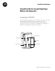
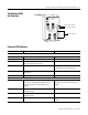
Installation Instructions ArmorPoint 24V dc 4-channel Digital Input Module with Diagnostics Catalog Number 1738-IB4DM12 The ArmorPoint™ I/O family consists of modular I/O modules. The sealed IP67 housing of these modules requires no enclosure. (Note that environmental requirements other than IP67 may require an additional appropriate housing.) I/O connectors are sealed M8 (pico), M12 (micro) or M23 styles. The mounting base ships with the module.
ArmorPoint 24V dc 4-channel Digital Input Module with Diagnostics Important User Information Solid state equipment has operational characteristics differing from those of electromechanical equipment. Safety Guidelines for the Application, Installation and Maintenance of Solid State Controls (publication SGI-1.1 available from your local Rockwell Automation sales office or online at http://literature.rockwellautomation.
ArmorPoint 24V dc 4-channel Digital Input Module with Diagnostics ATTENTION 3 Environment and Enclosure This equipment is intended for use in overvoltage Category II applications (as defined in IEC publication 60664-1), at altitudes up to 2000 meters without derating. This equipment is considered Group 1, Class A industrial equipment according to IEC/CISPR Publication 11.
ArmorPoint 24V dc 4-channel Digital Input Module with Diagnostics Mount the I/O Base To mount the base on a wall or panel, use the screw holes provided in the base. IMPORTANT The module must be mounted on a grounded metal mounting plate or other conductive surface. A drilling dimensions mounting illustration for the base with an adapter is shown below. Drilling Dimensions 1.9 in. 47.2 mm Adapter 2.0 in. 50 mm 0.87 in. 22 mm 2.0 in. 50 mm 0.87 in. 22 mm 2.0 in. 50 mm 4.02 in. 102 mm 1.81 in.
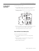
ArmorPoint 24V dc 4-channel Digital Input Module with Diagnostics Install the Digital Input Module 5 To install the digital input module: 1. Using a bladed screwdriver, rotate the keyswitch on the mounting base clockwise until the number 1 aligns with the notch in the base. 2. Position the module vertically above the mounting base. The module will bridge two bases. Module will bridge two bases.
ArmorPoint 24V dc 4-channel Digital Input Module with Diagnostics Understand Short-circuit Detection The sensor source voltage (SSV) for each input is protected against short circuits. For currents above 200 mA, a fault signal is issued and the input LED indicator is illuminated solid red. A thermally-actuated smart-power device or PTC is used as the protection means. On a per-input basis, the circuit and produced data automatically reset and SSV energizes upon removal of the short circuit.
ArmorPoint 24V dc 4-channel Digital Input Module with Diagnostics Wire the Module 7 Following are wiring instructions for the module. Make sure all connectors and caps are securely tightened to properly seal the connections against leaks and maintain IP enclosure type requirements. ATTENTION To comply with the CE Low Voltage Directive (LVD), all connected I/O must be powered from a source compliant with the following: • Safety Extra Low Voltage (SELV) or Protected Extra Low Voltage (PELV).
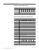
ArmorPoint 24V dc 4-channel Digital Input Module with Diagnostics Data Map - Produced Assembly Instance 23 Message Size: 1 Bytes 7 6 5 Produce 0 (Rx) Fault 3 Fault 2 Fault 1 Consume (Tx) No consumed data 4 3 Fault 0 2 Input 3 1 Input 2 Input 1 0 Input 0 Where: Fault = open wire or short circuit.
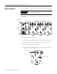
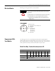
ArmorPoint 24V dc 4-channel Digital Input Module with Diagnostics Troubleshoot With the Indicators 9 1738-IB4DM12 1738-IB4DM12 24V dc In with Diagnostics 1 0 Module Status Indicators Network Status Indicators MOD NET IO Diagnostics: Solid Red = Short Flashing Red = Open 2 0 1 3 I/O Status Indicators 2 3 43680 Interpret LED Indicators Indication Probable Cause Recommended Action Off No power applied to device Apply power to device. Green Device operating normally None.
ArmorPoint 24V dc 4-channel Digital Input Module with Diagnostics Indication Probable Cause Recommended Action Red Critical link failure - failed communication device. Device detected error that prevents it from communicating on the network. Verify that adapter and terminal bases are properly installed, and reinstall, as needed. Flashing Red/Green Communication faulted device - the device has detected a network access error and is in communication faulted state.
ArmorPoint 24V dc 4-channel Digital Input Module with Diagnostics Specifications 11 Following are specifications for the ArmorPoint 24V dc 4-channel Digital Input Module. ArmorPoint 24V dc 4-channel Digital Input Module General Specifications Inputs Voltage, Off-State Input, Maximum Voltage, On-State Input Maximum Minimum Nominal Current, Off-State Input, Maximum Current, On-State Input Maximum Minimum Nominal 4 (1 group of 4) nonisolated, sinking 5V dc 28.8V dc 11V dc 24V dc 1.
ArmorPoint 24V dc 4-channel Digital Input Module with Diagnostics ArmorPoint 24V dc 4-channel Digital Input Module Environmental Specifications Operating Temperature Storage Temperature Relative Humidity Shock Vibration ESD Immunity Radiated RF Immunity EFT/B Immunity Surge Transient Immunity Conducted RF Immunity Emissions Publication 1738-IN021A-EN-E - January 2007 IEC 60068-2-1 (Test Ad, Operating Cold), IEC 60068-2-2 (Test Bd, Operating Dry Heat), IEC 60068-2-14 (Test Nb, Operating Thermal
ArmorPoint 24V dc 4-channel Digital Input Module with Diagnostics 13 ArmorPoint 24V dc 4-channel Digital Input Module Environmental Specifications (continued) Certifications Certifications:(2) (when product is marked) CE European Union 89/336/EEC EMC Directive, compliant with: EN 50082-2; Industrial Immunity EN 61326; Meas./Control/Lab.
Rockwell Automation Support Rockwell Automation provides technical information on the web to assist you in using its products. At http://support.rockwellautomation.com, you can find technical manuals, a knowledge base of FAQs, technical and application notes, sample code and links to software service packs, and a MySupport feature that you can customize to make the best use of these tools.