Installation Instructions ArmorPoint PROFIBUS Adapter, Series A Catalog Number 1738-APB Inside . . .
Important User Information Solid state equipment has operational characteristics differing from those of electromechanical equipment. Safety Guidelines for the Application, Installation and Maintenance of Solid State Controls (publication SGI-1.1 available from your local Rockwell Automation sales office or online at http://www.rockwellautomation.com/literature) describes some important differences between solid state equipment and hard-wired electromechanical devices.
Environment and Enclosure ATTENTION This equipment is intended for use in overvoltage Category II applications (as defined in IEC publication 60664-1), at altitudes up to 2000 meters without derating. This equipment is considered Group 1, Class A industrial equipment according to IEC/CISPR Publication 11. Without appropriate precautions, there may be potential difficulties ensuring electromagnetic compatibility in other environments due to conducted as well as radiated disturbance.
Prevent Electrostatic Discharge ATTENTION This equipment is sensitive to electrostatic discharge, which can cause internal damage and affect normal operation. Follow these guidelines when you handle this equipment: • Touch a grounded object to discharge potential static. • Wear an approved grounding wriststrap. • Do not touch connectors or pins on component boards. • Do not touch circuit components inside the equipment. • If available, use a static-safe workstation.
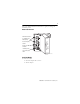
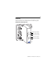
Refer to the Module Identification illustrations to guide you through the installation process.
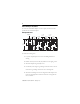
Mount the Adapter and I/O Bases To mount the ArmorPoint adapter on a wall or panel, use the screw holes provided in the ArmorPoint adapter. Drilling Dimensions Adapter 46.25 mm (1.8 in) 51.9 mm (2.0 in) 20.1 mm (0.8 in) 51.9 mm (2.0 in) 20.1 mm (0.8 in) 51.9 mm (2.0 in) 56 mm (2.2 in) 102 mm (4.02 in) 43769 To install the mounting base: 1. Layout the required points as shown in the Drilling Dimensions drawing. 2. Drill the necessary holes for #8 (M4) machine or self-tapping screws. 3.
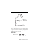
Terminating Bases Mounting Hole Ground Connection 43787 Latching Mechanism Set the Station Address To set the station address, adjust the switches on the front of the module (refer to the Module Identification illustration). Use a small blade screwdriver to rotate the switches. Line up the small notch on the switch with the number setting you wish to use. The two switches are most significant digit (MSD) and least significant digit (LSD). Valid address are from 01 to 99.
GSD File Requirements Current functionality of PROFIBUS adapters requires GSD files. These files are easy to install and are available online at: www.ab.com/networks/gsd/. Wire the Adapter Refer to the illustrations for wiring instructions for the adapter.
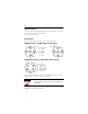
Troubleshoot To help you troubleshoot the adapter, refer to the Troubleshoot with the Indicators illustration and the individual indicator troubleshooting tables.
Adapter Status Indicator Refer to the table for a description of the Adapter Status indicator. Adapter Status Indicator State Status Off Off or Process in Progress Description • No power supplied. • Hardware check is in progress. Recommended Action Turn the adapter on or wait until the hardware check or initialization has finished. • Initialization is in progress. Green Operating Normally The adapter is operating normally. None. Red Hardware Check The adapter failed the hardware check.
PROFIBUS Status Indicator Refer to the table for a description of the PROFIBUS Status indicator. PROFIBUS Status Indicator State Status Off Off or Bus Offline Green Online The Bus is online and exchanging data. None. Flashing Green CLEAR Command Received Adapter has received a CLEAR command from the master. None. Red Initialization Error or No Module Flashing Red Configuration Error Description Recommended Action • No power supplied. • Bus is offline.
PointBus Status Indicator Refer to the table for a description of the PointBus Status indicator. PointBus Status Indicator State Status Off Off or Process in Progress Description • No power supplied. • Hardware check in progress. Recommended Action Turn the adapter on or wait until the hardware check or initialization has finished. • Initialization in progress. Green Operating Normally Flashing Red Incorrect or Missing I/O Module The adapter is operating normally.
System Power Indicator Refer to the table for a description of the System Power indicator. System Power Indicator State Status Description Recommended Action Off System Power Not Applied System power is not applied. Apply power. Green System Power Applied System power (5V) is present. None. Adapter Power Indicator Refer to the table for a description of the Adapter Power indicator.
Specifications ArmorPoint PROFIBUS Adapter - 1738-APB Specifications Specification Value Expansion I/O Capacity • PROFIBUS adapter backplane current output = 1.0 A max See the list of catalog numbers below for backplane current consumption and the current consumption for ArmorPoint modules connected to the ArmorPoint PROFIBUS adapter. Verify that it is below 1.0 A. • To extend backplane current to an additional 1.3 A, use a 1738-EP24DC Backplane Extension Power Supply.
ArmorPoint PROFIBUS Adapter - 1738-APB Specifications Field Power Bus Nominal Voltage Supply Voltage Supply Current 24V dc 10…28.8V dc range 10 A max Field Side Power Requirements, Max 24V dc (+20% = 28.8V dc) @ 400 mA Input Overvoltage Protection Reverse polarity protected Input Voltage Rating 24V dc nom 10…28.
ArmorPoint PROFIBUS Adapter - 1738-APB Specifications Power Consumption, Max 8.1 W @ 28.8V dc Power Dissipation, Max 2.8 W @ 28.8V dc Thermal Dissipation, Max 9.5 BTU/hr @ 28.8V dc Weight Metric 0.36 kg Weight Imperial 0.80 lb Wiring Category(1) 1 - on signal ports 1 - on communications ports (1) Use this Conductor Category information for planning conductor routing. Refer to Publication 1770-4.1, Industrial Automation Wiring and Grounding Guidelines.
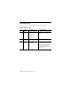
Environmental Specifications Radiated RF Immunity IEC 61000-4-3: 10V/m with 1 kHz sine-wave 80%AM from 30…2000 MHz 10V/m with 200 Hz 50% Pulse 100%AM at 900 Mhz 10V/m with 200 Hz 50% Pulse 100%AM at 1890 Mhz EFT/B Immunity IEC 61000-4-4: ±4 kV at 5 kHz on power ports ±2 kV at 5 kHz on communications ports Surge Transient Immunity IEC 61000-4-5: ±1 kV line-line(DM) and ±2 kV line-earth(CM) on power ports ±2 kV line-earth(CM) on shielded ports Conducted RF Immunity IEC 61000-4-6: 10Vrms with 1 kHz s
Notes: Publication 1738-IN015C-EN-E - February 2010
Notes: Publication 1738-IN015C-EN-E - February 2010
Rockwell Automation Support Rockwell Automation provides technical information on the Web to assist you in using its products. At http://support.rockwellautomation.com, you can find technical manuals, a knowledge base of FAQs, technical and application notes, sample code and links to software service packs, and a MySupport feature that you can customize to make the best use of these tools.