
User Manual User guide

24 Rockwell Automation Publication 1738-UM005A-EN-P - July 2013
Chapter 4 Configure the Adapter for Direct Connection in RSLogix 5000 Software
Set Up the Hardware
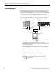
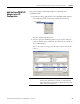
The following section describes how to set up the I/O Hardware.
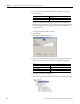
In this example, a ControlLogix chassis contains the Logix 63 controller in slot
1and a 1756-ENBT bridge module in slot 3. The 1738-AENT/B adapter is
mounted in slot 0, a 1738-IB4M12 input module is in slot 1, a 1738-OB4EM12
output module is in slot 2, a 1738-IE2CM12 module is in slot 3, and a
1738-OE2CM12 module is in slot 4.
To work along with this example, set up your system as shown in the figure.
• Note that in the example application, the L63 controller and
1756-ENBT bridge module (firmware version 2.3 or later) are assumed to
be in the slots shown above.
• Verify the IP addresses for your programming terminal, 1756-ENBT
bridge module, and 1738-AENT/B adapter.
• Verify the position (slot) of the I/O modules.
• Verify that all wiring and cabling is properly connected.
• Make sure your communication driver (for example, AB_ETH-1 or
AB-ETHIP-1) is configured in RSLinx software, as described in
Appendix C
in this manual.
32393
0
0
1
2
3
1
MOD
NET
1738-OB4EM12
24V dc Out
1738-AENT
Adapter
Status
Network
Activity
PointBus
Status
System
Power
Adapter
Power
EtherNet I/P
PWR
x1
x10
6
0
8
2
4
6
0
8
2
4
0
0
2
1
2
3
1
3
MOD
NET
1738-IB4M12
24V dc In
I
x100
6
0
8
2
4
Network
Status
conformance tested
™
P
A
E
D
D
R
S
S
0
02
1
MOD
NET
1738-OE2CM12
Analog Current Out
0
0
1
1
MOD
NET
1738-IE2CM12
Analog Current In
2
3
Local Chassis
ArmorPOINT I/O
L63
Controller (slot 1)
1756-ENBT
10.88.70.90 (slot 3)
Data
Switch
10.88.70.26
Programming
Terminal
1738-AENT/B
10.88.70.2
Slot 0 1 2 3