User Manual 1738 ArmorPOINT I/O EtherNet/IP Adapters Catalog Numbers 1738-AENT, Series B
Important User Information Solid-state equipment has operational characteristics differing from those of electromechanical equipment. Safety Guidelines for the Application, Installation and Maintenance of Solid State Controls (publication SGI-1.1 available from your local Rockwell Automation sales office or online at http://www.rockwellautomation.com/literature/) describes some important differences between solid-state equipment and hard-wired electromechanical devices.
Preface Read this preface to familiarize yourself with the rest of the manual. It provides information concerning: • who should use this manual • the purpose of this manual • related documentation • conventions used in this manual Who Should Use this Manual This manual is intended for control engineers and technicians who are installing, configuring, maintaining, and troubleshooting an EtherNet/IP control system that communicates with ArmorPOINT I/O® through a 1738-AENT Series B adapter.
Resource Description EtherNet/IP Embedded Switch Technology Application Guide, publication ENET-AP005 An application guide describing how to install, configure and maintain linear and Device-level Ring (DLR) networks using Rockwell Automation EtherNet/IP devices with embedded switch technology. Allen-Bradley Industrial Automation Glossary, publication AG-QR071 A glossary of industrial automation terms and abbreviations. Industrial Automation Wiring and Grounding Guidelines, publication 1770-IN041.
Common Techniques Used in this Manual The following conventions are used throughout this manual: • Bulleted lists such as this one provide information, not procedural steps. • Numbered lists provide sequential steps or hierarchical information. • Italic type is used for emphasis. Rockwell Software products contain extensive tutorials and help screens. We recommend that you use these tutorials and help screens to learn about the products.
System Components We used the following components for the example applications. You will need the same or similar components to set up your own control system using ArmorPoint I/O on EtherNet/IP.
Table of Contents Preface Who Should Use this Manual . . . . . . . . . . . . . . . . . . . . . . . . . . . . . . . . . . . . . . . i Purpose of This Manual . . . . . . . . . . . . . . . . . . . . . . . . . . . . . . . . . . . . . . . . . . . . i Related Documentation. . . . . . . . . . . . . . . . . . . . . . . . . . . . . . . . . . . . . . . . . i Additional Resources . . . . . . . . . . . . . . . . . . . . . . . . . . . . . . . . . . . . . . . . . . . . . . ii Terminology. . . . . . . . . . . . . . . . .
Table of Contents Chapter 3 Configure the Adapter with RSLogix5000 software Introduction . . . . . . . . . . . . . . . . . . . . . . . . . . . . . . . . . . . . . . . . . . . . . . . . . . . . . . 1 Configuration Requirements . . . . . . . . . . . . . . . . . . . . . . . . . . . . . . . . . . . . . . . 2 IP Address . . . . . . . . . . . . . . . . . . . . . . . . . . . . . . . . . . . . . . . . . . . . . . . . . . . . 2 Gateway Address . . . . . . . . . . . . . . . . . . . . . . . . . . . . . . . . . . . .
Table of Contents Chapter 5 Configure the Adapter for Direct Connection and Rack Optimization in RSLogix 5000 Software Overview . . . . . . . . . . . . . . . . . . . . . . . . . . . . . . . . . . . . . . . . . . . . . . . . . . . . . . . . Set Up the Hardware . . . . . . . . . . . . . . . . . . . . . . . . . . . . . . . . . . . . . . . . . . . . . Set Up the ArmorPOINT I/O Hardware . . . . . . . . . . . . . . . . . . . . . . Create the Example Application . . . . . . . . . . . . . . . . . . . . . . . . . .
Table of Contents Use the Network Settings Page. . . . . . . . . . . . . . . . . . . . . . . . . . . . . . . . . Use the Ethernet Statistics Page . . . . . . . . . . . . . . . . . . . . . . . . . . . . . . . . Use the I/O Connections Page. . . . . . . . . . . . . . . . . . . . . . . . . . . . . . . . . Use the Advanced Diagnostics Page . . . . . . . . . . . . . . . . . . . . . . . . . . . . Work with the Configuration Pages. . . . . . . . . . . . . . . . . . . . . . . . . . . . . . . .
Chapter 1 Overview of the 1738 ArmorPOINT I/O EtherNet/IP Adapter Overview This chapter provides an overview of the ArmorPOINT I/O Series B EtherNet/IP adapter, its primary features, and how to use it. You need to understand the concepts discussed in this chapter to configure your adapter and use it in an EtherNet/IP control system. The following table lists where to find specific information.
Chapter 1 Overview of the 1738 ArmorPOINT I/O EtherNet/IP Adapter • Half/full duplex 10 Mbit or 100 Mbit operation • Panel or wall mounting • Communication to and from other ArmorPOINT I/O modules in the chassis • Communication supported by RSLinx software • IP address assigned via standard BootP or DHCP tools • I/O configuration via RSLogix 5000 software • No network scheduling required • No routing tables required • Support of connections from multiple controllers simultaneously You must use RSLogix 500
Overview of the 1738 ArmorPOINT I/O EtherNet/IP Adapter Physical Features of Your Adapter Chapter 1 The 1738 Adapter has the following components: • One EtherNet/IP Female M12 connector • Network address Switches • Mini Style 4-Pin in Male Auxiliary Power Connector • Status indicators (Module Status; Network Status; POINTBus Status; Network Activity; System Power; Adapter Power) Physical Features of the 1738-AENT/B Adapters EtherNet I/P M12 Female in connector 1738-AENT Series B X100 I P X10 Network
Chapter 1 Overview of the 1738 ArmorPOINT I/O EtherNet/IP Adapter Important Adapter Considerations Before you begin using your adapter, note the following important considerations. Set the Chassis Size The ArmorPOINT I/O adapters require configuration of their chassis size before you can make any I/O connections. The factory default setting for the chassis size is one slot, which represents the adapter by itself.
Overview of the 1738 ArmorPOINT I/O EtherNet/IP Adapter • • • • • • Chapter 1 – It cannot assume any safe operation until there is a match between the number of modules indicating their presence in the chassis and what the adapter has saved in non-volatile memory because it cannot detect empty terminal bases. – Actual module identification (such as, electronic keying) is done when connection establishment requests are received from the controller or controllers.
Chapter 1 Overview of the 1738 ArmorPOINT I/O EtherNet/IP Adapter Use of the Common Industrial Protocol (CIP) The adapter uses the Common Industrial Protocol (CIP). CIP is the application layer protocol specified for EtherNet/IP, the Ethernet Industrial Protocol, as well as for ControlNet and DeviceNet networks. It is a message-based protocol that implements a relative path to send a message from the producing device in a system to the consuming devices.
Overview of the 1738 ArmorPOINT I/O EtherNet/IP Adapter Chapter 1 every 50 ms the device should send its data to the controller and the controller should send the consumed (output) data to the device. Use RPIs only for devices that exchange data. For example, a ControlLogix EtherNet/IP bridge module in the same chassis as the controller does not require an RPI, because it is not a data-producing member of the system. Its use is only as a bridge to remote racks.
Chapter 1 Overview of the 1738 ArmorPOINT I/O EtherNet/IP Adapter Mixing Rack-optimized and Direct Connections You can mix communication formats for different I/O modules communicating through the same adapter. I/O modules set up to use rack optimization communicate at the rate of the RPI configured for the adapter. I/O modules configured for direct communication communicate at their own individual RPIs and ignore the rack-optimized RPI.
Chapter 2 Install Your ArmorPOINT I/O Adapter Overview This chapter describes how to install and wire your module.
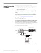
Chapter 2 Install Your ArmorPOINT I/O Adapter Mount the Adapter and I/O Base To mount the adapter on a wall or panel, use the screw holes provided in the adapter. A mounting illustration for the adapter with several attached I/O bases is shown below. Mounting illustration for the ArmorPOINT adapter and I/O Mounting bases Adapter 46.2 mm (1.82 in) 52 mm (2.05 in) 52 mm (2.05 in) 20 mm (0.79 in) 20 mm (0.79 in) 52 mm (2.05 in) 56 mm (2.20 in) 102 mm (4.02 in.
Install Your ArmorPOINT I/O Adapter Chapter 2 7. Set the network rotary switches to the desired value. See Set the Network Address for ArmorPOINT I/O Adapters in Chapter 3 for details on setting the IP address. Install the ArmorPOINT I/O Modules To install the ArmorPOINT I/O modules, 1. Using a bladed screwdriver, rotate the keyswitch on the I/O module mounting base clockwise until the appropriate number for the I/O module you are installing aligns with the notch in the I/O module mounting base. 2.
Chapter 2 Install Your ArmorPOINT I/O Adapter Wire the Adapter Wire an ArmorPOINT I/O Adapter Refer to the following illustration to wire the adapter EtherNet/IP Connectors M12 Female in Connector 43765 (view into connector) Pin 1 - Tx + Pin 2 - Rx + Pin 3 - Tx Pin 4 - Rx - Auxiliary Power Connector (1) Mini Style 4-Pin in Male Connector (view into connector) Pin 1 - User Power + Pin 2 - Adapter Power + Pin 3 - Adapter Power Pin 4 - User Power 43587 ATTENTION: Make sure all connectors and caps are se
Chapter 3 Configure the Adapter with RSLogix5000 software Introduction This chapter guides you through the steps required to configure your modules using the RSLogix 5000 software. Note that the modules presented in this chapter can be configured using RSLogix 5000 software, version 17, or later. Before using your adapter in an EtherNet/IP network, you need to configure it with an IP address, subnet mask, and optional Gateway address.
Chapter 3 Configure the Adapter with RSLogix5000 software Configuration Requirements Before you can use your adapter, you must configure its IP address, its subnet mask, and, optionally, a gateway address. You can use the Rockwell BootP utility, version 2.3 or later, to perform the configuration. You can also use a DHCP server or the network address rotary switches to configure these parameters. If using the BootP/DHCP utility, you will need to know the Ethernet hardware address of your module.
Configure the Adapter with RSLogix5000 software Chapter 3 IP addresses are written as four decimal integers (0…255) separated by periods where each integer gives the value of one byte of the IP address. EXAMPLE For example, the 32-bit IP address: 10000000 00000001 00000000 00000001 is written as 128.1.0.1 Gateway Address This section applies to multi-network systems. If you have a single network system, refer to the next section. The Gateway Address is the default address of a network.
Chapter 3 Configure the Adapter with RSLogix5000 software Subnet Mask The subnet mask is used for splitting IP networks into a series of subgroups, or subnets. The mask is a binary pattern that is matched up with the IP address to turn part of the Host ID address field into a field for subnets. EXAMPLE Take Network 2 (a Class B network) in the previous example and add another physical network.
Configure the Adapter with RSLogix5000 software Set the Network Address Chapter 3 The adapters ship DHCP-enabled and with the switches set to 999. You can set the network Internet Protocol (IP) address as follows.
Chapter 3 Configure the Adapter with RSLogix5000 software Use the Rockwell BootP/ DHCP Utility The Rockwell BootP/DHCP utility is a standalone program that incorporates the functionality of standard BootP software with a user-friendly graphical interface. It is located in the Utils directory on the RSLogix5000 software installation CD. The adapter must have DHCP enabled (factory default and the network address switches set to an invalid value) to use the utility.
Configure the Adapter with RSLogix5000 software Chapter 3 2. Double-click the hardware address of the device you want to configure. The New Entry dialog appears with the device’s Ethernet Address (MAC).
Chapter 3 Configure the Adapter with RSLogix5000 software 3. Enter the IP Address you want to assign to the device and click OK. The device is added to the Relation List, displaying the Ethernet Address (MAC) and corresponding IP Address, Hostname, and Description (if applicable). When the address displays in the IP Address column in the Request History section, the IP address assignment has been made. 4.
Configure the Adapter with RSLogix5000 software Chapter 3 Save the Relation List You can save the Relation List for later use. To save the Relation List, perform the following steps: 1. Select Save As... from the File menu. The Save As dialog appears. 2. Select the folder where you want to save the Relation List. 3. Enter a File name for the Relation List, for example, control system configuration, and click Save. You can leave the Save as type at the default setting: Bootp Config Files (*.bpc).
Chapter 3 Configure the Adapter with RSLogix5000 software Use DHCP Software to Configure Your Adapter DHCP (Dynamic Host Configuration Protocol) software automatically assigns IP addresses to client stations logging onto a TCP/IP network. DHCP is based on BootP and maintains some backward compatibility. The main difference is that BootP was designed for manual configuration, while DHCP allows for dynamic allocation of network addresses and configurations to newly attached devices.
Chapter 4 Configure the Adapter for Direct Connection in RSLogix 5000 Software Overview In this example, a ControlLogix controller communicates with ArmorPOINT I/O modules via the adapter using a direct connection. The adapter makes a direct connection to each of the modules referenced by the data. The modules presented in this chapter use RSLogix 5000 software, revision 17 and above.
Chapter 4 Configure the Adapter for Direct Connection in RSLogix 5000 Software Set Up the Hardware The following section describes how to set up the I/O Hardware. In this example, a ControlLogix chassis contains the Logix 63 controller in slot 1and a 1756-ENBT bridge module in slot 3. The 1738-AENT/B adapter is mounted in slot 0, a 1738-IB4M12 input module is in slot 1, a 1738-OB4EM12 output module is in slot 2, a 1738-IE2CM12 module is in slot 3, and a 1738-OE2CM12 module is in slot 4.
Configure the Adapter for Direct Connection in RSLogix 5000 Software Create the Example Application Chapter 4 Perform the following steps to create the example application: 1. Start RSLogix 5000 Enterprise Series software. The RSLogix 5000 main dialog opens. 2. From the File menu, select New. The New Controller dialog opens. 3. Enter an appropriate Name for the Controller, for example, ArmorPOINT_IO_Controller. 4.
Chapter 4 Configure the Adapter for Direct Connection in RSLogix 5000 Software Configure the I/O Modules You now add the ArmorPOINT I/O modules to the controller’s I/O configuration performing these procedures: • Add the local 1756-ENBT module to the I/O configuration. • Add the 1738-AENT/B adapter as a child of the 1756-ENBT module on the Ethernet network. • Add the ArmorPOINT I/O modules as children of the adapter.
Configure the Adapter for Direct Connection in RSLogix 5000 Software Chapter 4 The Select Module Type dialog opens. 2. Select the appropriate Module Type filter Category (for the example we selected Communication), and Module Type Vendor (for the example we selected Allen-Bradley).
Chapter 4 Configure the Adapter for Direct Connection in RSLogix 5000 Software 4. Enter values for Name, IP Address, and Slot, noting that we used the following values: Name IP Address Slot Local_ENBT 10.88.70.4 3 Note the module definition properties on the bottom left of the New Module dialog. You have the option to change these properties by clicking the Change button. Some of the properties cannot be modified while pending edits exists. To change the default module properties, 5. Click Change...
Configure the Adapter for Direct Connection in RSLogix 5000 Software Add the ArmorPOINT I/O Adapter to the I/O Configuration Chapter 4 Next, you must add the 1738-AENT/B adapter as a child of the local 1756-ENBT module. 1. In the Project dialog, right-click the local 1756-ENBT module under the I/O Configuration folder, and select New Module from the dialog. The Select Module Type dialog opens. 2.
Chapter 4 Configure the Adapter for Direct Connection in RSLogix 5000 Software 3. Select your adapter from the list and click Create. The New Module dialog opens. 4. Select the General Tab and enter the module details, noting that we used the following values. Name ArmorPoint IO Adapter IP Address 10.88.70.2 IMPORTANT Note that the slot field is disabled because the slot is automatically 0 for the 1738-AENT adapter. Note the module definition properties on the bottom left of the New Module dialog.
Configure the Adapter for Direct Connection in RSLogix 5000 Software Chapter 4 6. Choose values for Series, Revision, Electronic Keying, Connection, and Chassis Size, noting that we used the following values: Series Connection Chassis Size Electronic Keying Revision IMPORTANT B None 5 Compatible Module 4.3 The chassis size value equals 1 for the adapter plus the number of I/O modules installed (physically present on the I/O backplane).
Chapter 4 Configure the Adapter for Direct Connection in RSLogix 5000 Software Add the ArmorPoint I/O Modules to the I/O Configuration You now add the ArmorPoint I/O modules to the I/O Configuration List under the adapter. In this example, you add a 1738-IB4M12 24V DC digital input module, a 1738-OB4EM12 24V DC digital output module, a 1738-IE2CM12 analog current input module, and a 1738-OE2CM12 analog current output module with standard configurations.
Configure the Adapter for Direct Connection in RSLogix 5000 Software Chapter 4 3. From the modules listed select the 1738-IB4M12 module and click Create. The New Module dialog opens. 4.
Chapter 4 Configure the Adapter for Direct Connection in RSLogix 5000 Software 5. Choose the Connection tab to set the RPI value. RPI is selectable since it is a direct connection Note that the RPI is selectable and has a default value. Because we are making a direct connection to each I/O module, we must specify an RPI to determine how often the data is exchanged with the 1738-AENT/B adapter for each module. 6. Enter 20 ms as the RPI for the 1738-IB4M12 module. 7. Click OK to save the configuration.
Configure the Adapter for Direct Connection in RSLogix 5000 Software Chapter 4 Add the Digital Output Module 1. Highlight the 1738-AENT/B adapter under the I/O Configuration folder, right-click and select New Module. IMPORTANT If the 1738-AENT/B chassis base size is exceeded, (that is, you try to add more modules than you configured) the New Module selection is dimmed out and disabled. You are not able to add any more ArmorPoint I/O modules until the 1738-AENT/B chassis base size is increased.
Chapter 4 Configure the Adapter for Direct Connection in RSLogix 5000 Software 4. Enter values for Name and Slot, noting that we used the following values. Name Slot ArmorPOINT_Digital_Output 2 5. Choose the Connection tab to set the RPI value. The RPI is selectable since it is a direct connection 6. Enter 20 ms as the RPI for the 1738-IB4M12 module to set how often you exchange data with the I/O adapter. Note that the RPI is selectable on the screen and has a default value of 20.0 ms.
Configure the Adapter for Direct Connection in RSLogix 5000 Software Chapter 4 7. Click OK to save the configuration. The digital output module appears in the I/O configuration indented under the 1738-AENT/B adapter. Add the Analog Current Input Module 1. Highlight the 1738-AENT/B adapter under the I/O Configuration folder, right-click and select New Module.
Chapter 4 Configure the Adapter for Direct Connection in RSLogix 5000 Software 3. From the modules listed select the 1738-IE2CM12 module and click Create. The New Module dialog opens. 4. Enter values for Name and Slot, noting that we used the following values .
Configure the Adapter for Direct Connection in RSLogix 5000 Software Chapter 4 5. Choose the Connection tab to set the RPI value. RPI is selectable since it is a direct connection. Note that the RPI is selectable on the screen and has a default value of 80.0 ms. The 1738-IE2CM12 module is an analog module and, therefore, an RPI value must be assigned. 6. Select 50.0 for the RPI to set how often the data is exchanged with the 1738-AENT/B adapter.
Chapter 4 Configure the Adapter for Direct Connection in RSLogix 5000 Software Add the Analog Current Output Module 1. Highlight the 1738-AENT/B adapter under the I/O Configuration folder, right-click and select New Module. IMPORTANT If the 1738-AENT/B chassis base size is exceeded, (that is, you try to add more modules than you configured) the New Module selection is dimmed out and disabled. You are not able to add any more ArmorPoint I/O modules until the 1738-AENT/B chassis base size is increased.
Configure the Adapter for Direct Connection in RSLogix 5000 Software Chapter 4 4. The New Module dialog opens. 5. Enter values for Name, Slot, noting that we used the following values . Name Slot ArmorPOINT_Analog_Current_Output 4 6. Choose the Connection tab to set the RPI value. The RPI is selectable since it is a direct connection. Note that the RPI is selectable on the screen and has a default value of 80.0 ms.
Chapter 4 Configure the Adapter for Direct Connection in RSLogix 5000 Software 8. Click OK to save the configuration. The analog current output module appears in the I/O Configuration indented under the 1738-AENT/B adapter.
Configure the Adapter for Direct Connection in RSLogix 5000 Software Edit the Controller Tags Chapter 4 When you add modules to the I/O configuration, the system creates tags for those modules to use in the application program. For the example application, you need to add one more Controller Tag. 1. Double-click the Controller Tags folder in the project window. The Controller Tags dialog opens. You see the tags created for the 1738-AENT/B adapter and its I/O modules.
Chapter 4 Configure the Adapter for Direct Connection in RSLogix 5000 Software 2. Click the Edit Tags tab at the bottom of the Controller Tags dialog and create the following tag: Create the Ladder Program Tag Type Parts_Count Counter Next, create the example ladder program to test the I/O. 1. Under the MainProgram folder, double-click MainRoutine.
Configure the Adapter for Direct Connection in RSLogix 5000 Software Chapter 4 2. Enter the following ladder program using the tags previously created. 3. Save the program. Download the Program to the Controller Follow this procedure to download the program we just saved to the ControlLogix controller. 1. From the main menu, choose Communications>Who Active. 2. Navigate to select the slot where the controller is located in the chassis. 3. Choose Set Project Path.
Chapter 4 Configure the Adapter for Direct Connection in RSLogix 5000 Software 4. Choose Download for both instances. Notice that the 1756-ENBT Bridge is now online. If yellow triangles are present, see the following section. Verify the Module Chassis Size You have now built the I/O tree in RSLogix 5000 software and the RSLogix 5000 software used the chassis size from the 1738-AENT/B adapter General tab. Now you need to download this new chassis size value into the 1738-AENT/B adapter hardware.
Configure the Adapter for Direct Connection in RSLogix 5000 Software Chapter 4 You see the Module Fault error code. 5. Click the Chassis Size tab. 6. Click Set Chassis Size in Module. Value from RSLogix 5000 Value stored in 1738-AENT 7. Read and acknowledge the warning screen. 8. Click OK to continue.
Chapter 4 Configure the Adapter for Direct Connection in RSLogix 5000 Software Notice the chassis size in the module has been modified to 5. 9. Click OK to close the dialog. At this point, verify that your PointBus status LED is solid green and that all the yellow triangles in your I/O configuration are gone. 10. Click File>Save to save the project.
Configure the Adapter for Direct Connection in RSLogix 5000 Software Configure the Adapter with Fixed IP Address Chapter 4 To configure the adapter with a fixed IP address to prevent the adapter from ceasing to communicate with the ControlLogix controller: 1. All controllers with I/O connections to the AENTR and/or the modules in its backplane need to be in program mode. 2. In the Module Properties dialog, click the Internet Protocol tab. 3. If it is not selected, select Manually configure IP settings.
Chapter 4 Configure the Adapter for Direct Connection in RSLogix 5000 Software Chapter Summary 50 In this chapter, you learned how to configure the 1738-AENT/B adapter using a direct connection and how to configure the adapter for a fixed IP address. The following chapter describes an example application in which you configure I/O using a direct connection and a rack-optimized connection.
Chapter 5 Configure the Adapter for Direct Connection and Rack Optimization in RSLogix 5000 Software Overview .This chapter guides you through the steps required to configure your 1738 ArmorPOINT I/O Ethernet Adapter for both direct connection and rack optimization using RSLogix 5000 software. It is possible to mix communication formats for different I/O modules communicating through the same adapter.
Chapter 5 Configure the Adapter for Direct Connection and Rack Optimization in RSLogix 5000 Software Set Up the Hardware The following section describe how to set up the I/O Hardware. Set Up the ArmorPOINT I/O Hardware In this example, a ControlLogix chassis contains the L63 controller in slot 1 and a 1756-ENBT bridge module in slot 3.
Configure the Adapter for Direct Connection and Rack Optimization in RSLogix 5000 Software Create the Example Application Chapter 5 Perform the following steps to create the example application: 1. Start the RSLogix 5000 Enterprise Series software. The RSLogix 5000 software main dialog opens. 2. From the File menu, select New. 3. The New Controller dialog opens. 4. Enter an appropriate Name for the Controller, for example, POINT_IO_Controller. 5.
Chapter 5 Configure the Adapter for Direct Connection and Rack Optimization in RSLogix 5000 Software Configure the I/O Modules You now add the ArmorPOINT I/O modules to the controller’s I/O configuration performing these procedures: • Add the local 1756-ENBT module to the I/O configuration. • Add the 1738-AENT/B adapter as a child of the 1756-ENBT module on the Ethernet network. • Add the ArmorPOINT I/O modules as children of the 1738-AENT/B adapter.
Configure the Adapter for Direct Connection and Rack Optimization in RSLogix 5000 Software Chapter 5 The Select Module Type dialog opens. 2. Select the appropriate Module Type filter Category (for the example we selected Communication), and Module Type Vendor (for the example we selected Allen-Bradley).
Chapter 5 Configure the Adapter for Direct Connection and Rack Optimization in RSLogix 5000 Software 4. Enter values for Name, IP Address, and Slot, noting that we used the following values: Name IP Address Slot Local_ENBT 10.88.70.4 3 Note the module definition properties on the bottom left of the New Module dialog. You have the option to change these properties by clicking the Change button. Some of the properties cannot be modified while pending edits exists.
Configure the Adapter for Direct Connection and Rack Optimization in RSLogix 5000 Software Add the ArmorPOINT I/O Adapter to the I/O Configuration Chapter 5 Next, you must add the 1738-AENT/B adapter as a child of the local 1756-ENBT bridge module. 1. In the Project dialog, right-click the local 1756-ENBT bridge module under the I/O Configuration folder and select New Module from the dialog. 2. The Select Module Type dialog opens.
Chapter 5 Configure the Adapter for Direct Connection and Rack Optimization in RSLogix 5000 Software 3. Select the 1738-AENT/B adapter from the list and click Create. The New Module dialog opens. 4. Enter values for Name and IP address, noting we used the following values. . Name ArmorPoint IO Adapter IP Address 10.88.70.2 IMPORTANT Note that the slot field is disabled because the slot is automatically 0 for the I/O adapter. 5. Click Change... The Module Definition dialog opens.
Configure the Adapter for Direct Connection and Rack Optimization in RSLogix 5000 Software Chapter 5 6. Enter or select values for Series, Revision, Electronic Keying, Connection, and Chassis Size, noting that we used the following values: Series Connection Chassis Size Electronic Keying Revision IMPORTANT B Rack Optimization 5 Compatible Module 4.3 The chassis size value equals 1 for the adapter plus the number of I/O modules installed (physically present on the I/O backplane).
Chapter 5 Configure the Adapter for Direct Connection and Rack Optimization in RSLogix 5000 Software 9. In the New Module screen select the Connection Tab. 10. Verify that the Requested Packet Interval (RPI) used for the rackoptimized connection to the I/O modules is appropriate for your system (20.0 ms for this example). If not, change it to the correct value. IMPORTANT To avoid overloading the adapter, it is recommended that the RPI be no less than 10.0 ms for rack connections and 50.
Configure the Adapter for Direct Connection and Rack Optimization in RSLogix 5000 Software Chapter 5 Add the ArmorPoint Digital Modules and Configure For Rack Optimization Connection You must now add the ArmorPoint I/O modules to the I/O Configuration List under the adapter. In this example, you add a 1738-IB4M12 24V DC digital input module, a 1738-OB4EM12 24V DC digital output, a 1738-IE2CM12 analog currentinput module, and a 1738-OE2CM12 analog current output module.
Chapter 5 Configure the Adapter for Direct Connection and Rack Optimization in RSLogix 5000 Software 3. From the modules listed select the 1738-IB4M12 module and click Create. TIP In the Select Module Type dialog, you have options to search for a specific module, add modules to a Favorites list, filter by Category and/or Vendor, Hide and Show Filters, use Module Discovery, sort by vendor, or access your Favorites list. The New Module dialog opens. 4.
Configure the Adapter for Direct Connection and Rack Optimization in RSLogix 5000 Software Chapter 5 6. Change the Connection from Data to Rack Optimization and click OK. 7. In the New Module screen, click OK to accept the configuration. The digital input module appears in the I/O configuration indented under the 1738-AENT/B adapter. Add The Digital Output Module 1. Highlight the 1738-AENT/B adapter under the I/O Configuration folder, right-click and select New Module.
Chapter 5 Configure the Adapter for Direct Connection and Rack Optimization in RSLogix 5000 Software 2. Select the appropriate filter for Module Type Category (for the example we selected Digital) and Module Type Vendor (for the example we selected Allen-Bradley). Note: to select only one category you will need to unselect those already selected. 3. Choose the 1738-OB4EM12 module from the list and click Create. 4.
Configure the Adapter for Direct Connection and Rack Optimization in RSLogix 5000 Software Chapter 5 The digital output module appears in the I/O configuration indented under the 1738-AENT/B adapter. Add the ArmorPoint Analog Modules and Configure For Direct Connection Analog and specialty modules must be configured for direct connection. Refer to the following procedure to add the 1738-IE2CM12 and the 1738-OE2CM12 analog modules to the I/O configuration. Add the Analog Current Input Module 1.
Chapter 5 Configure the Adapter for Direct Connection and Rack Optimization in RSLogix 5000 Software 3. From the modules listed select the 1738-IE2CM12 and click Create. TIP In the Select Module Type dialog, you have options to search for a specific module, add modules to a Favorites list, filter by Category and/or Vendor, Hide and Show Filters, use Module Discovery, sort by vendor, or access your Favorites list. The New Module dialog opens. 4.
Configure the Adapter for Direct Connection and Rack Optimization in RSLogix 5000 Software Chapter 5 5. Select the Connection tab to set the RPI value. RPI is selectable since it is a direct connection. Note that RPI is selectable on the screen because you are adding an analog module and an RPI value must be assigned for the module. 6. Enter 50.0 for the RPI and click OK to save the configuration. IMPORTANT To avoid overloading the 1738-AENT/B adapter, it is recommended that the RPI be no less than 50.
Chapter 5 Configure the Adapter for Direct Connection and Rack Optimization in RSLogix 5000 Software The Select Module dialog opens. 2. Select the appropriate filter for Module Type Category (for the example we selected Analog) and Module Type Vendor (for the example we selected Allen-Bradley). Note: to select only one category you will need to unselect those already selected. 3. Choose the 1738-OE2CM12 module from the list and click Create.
Configure the Adapter for Direct Connection and Rack Optimization in RSLogix 5000 Software Chapter 5 4. Enter values for Name and Slot, noting that we used the following values Name Slot ArmorPoint Analog Current Output 4 Note the module definition properties on the bottom left of the New Module dialog. You have the option to change these properties by clicking the Change... button. Some of the properties cannot be modified while pending edits exist. 5. Select Change...
Chapter 5 Configure the Adapter for Direct Connection and Rack Optimization in RSLogix 5000 Software 8. Enter 50.0 for the RPI and click OK to save the configuration. IMPORTANT To avoid overloading the 1738-AENT/B adapter, it is recommended that the RPI be no less than 50.0 ms. 9. Click OK to save the configuration. 10.
Configure the Adapter for Direct Connection and Rack Optimization in RSLogix 5000 Software Download the Program to the Controller Chapter 5 Follow this procedure to download the program we just saved to the ControlLogix controller. 1. From the main menu, choose Communications>Who Active. 2. Navigate to select the slot where the controller is located in the chassis. 3. Choose Set Project Path. 4. Choose Download for both instances. Notice that the 1756-ENBT Bridge is now online.
Chapter 5 Configure the Adapter for Direct Connection and Rack Optimization in RSLogix 5000 Software Verify the Module Chassis Size You have now built the I/O tree in RSLogix 5000 software and the RSLogix 5000 software used the chassis size from the 1738-AENT/B adapter General tab. Now you need to download this new chassis size value into the 1738-AENT/B adapter hardware. This procedure will synchronize the chassis size value from the RSLogix 5000 software into the 1738-AENT/B adapter hardware.
Configure the Adapter for Direct Connection and Rack Optimization in RSLogix 5000 Software Chapter 5 7. Read and acknowledge the warning screen. 8. Click OK to continue. Notice the chassis size in the module has been modified to 5. 9. Click OK to close the dialog. At this point, verify that your POINTBus status LED is solid green and that all the yellow triangles in your I/O configuration are gone. 10. Click File>Save to save the project.
Chapter 5 Configure the Adapter for Direct Connection and Rack Optimization in RSLogix 5000 Software An Overloaded 1738-AENT/B Adapter Each ArmorPOINT I/O connection established with the 1738-AENT/B adapter will consume a portion of the microprocessor’s bandwidth. The amount of bandwidth used by a connection depends on a number of variables, including the RPI, the number of ArmorPOINT I/O modules involved in the connection, and the rate of change of the I/O.
Configure the Adapter for Direct Connection and Rack Optimization in RSLogix 5000 Software Access Module Data via the 1738-AENT/B Adapter Chapter 5 Use the following information for 1738 ArmorPOINT I/O Ethernet adapter data in the ladder logic program.
Chapter 5 Configure the Adapter for Direct Connection and Rack Optimization in RSLogix 5000 Software Notes: 76 Rockwell Automation Publication 1738-UM005A-EN-P - July 2013
Chapter 6 Troubleshoot the Adapter This chapter describes the different status indicators available in the 1738 ArmorPOINT I/O EtherNet/IP adapter and how to interpret these indicators to help troubleshoot the module.
Chapter 6 Troubleshoot the Adapter Status Indicators for 1738-AENT/B Adapter Indicator Status Description Adapter Status Off No power applied to device Flashing green Device needs commissioning due to missing, incomplete, or incorrect configuration. Solid green Device operating normally Flashing red Recoverable fault. Complete firmware update, verify address switches. Solid red Unrecoverable fault has occurred: • self test failure (checksum failure at power cycle, ramtest) at power cycle.
Troubleshoot the Adapter Chapter 6 Notes: Rockwell Automation Publication 1738-UM005A-EN-P - July 2013 77
Chapter 6 78 Troubleshoot the Adapter Rockwell Automation Publication 1738-UM005A-EN-P - July 2013
Appendix A Specifications General Specifications The 1738-AENT/B adapters have the following general specifications. General Specifications Attributes Description Expansion I/O capacity, max 63 modules •5 rack-optimized connections (for digital modules only) •31 direct connections •1738-AENT/B backplane current output = 1.0 A. •Actual number of modules can vary. •Add up current requirements of modules you want to use to make sure they do not exceed the amperage limit of 1.
Appendix A Specifications General Specifications Attributes Description Status indicators 3 red/green status indicators on CPU: • Adapter Status • Network Status • POINTBus Status 1 green status indicator on CPU: • Network Activity 2 green power supply status indicators on DC-DC Converter: • System Power (5V DC to POINTBus Out) • Adapter Power (24V DC from Field In) Power consumption, max 8.1 W @ 28.8V DC Wiring category(1) 1 – on power ports 1 – on communications ports Power dissipation, max 2.
Specifications Appendix A Power Supply Specifications Attributes Description POINTBus output current, max Auxiliary power cable (1) Interruption (1) EtherNet Communication 5V DC @ 1.0A Standard cordset (single-ended), for example Allen-Bradley part number 889N-F4AFC-6F or 889N-R4AFC-6F. Standard patchcord (double-ended), for example, Allen-Bradley part number 889N-F4AFNU-6F or 889N-F4AFNV-6F.
Appendix A Specifications Environmental Specifications Certifications Attributes Description Shock, nonoperating IEC60068-2-27 (Test Ea, Unpackaged Shock): 50 g Emissions CISPR 11: Class A ESD immunity IEC 61000-4-2: 6 kV contact discharges 8 kV air discharges Radiated RF immunity IEC 61000-4-3: 10V/m with 1 kHz sine-wave 80% AM from 80...2000 MHz 10V/m with 200 Hz 50% Pulse 100% AM @ 900 MHz 10V/m with 200 Hz 50% Pulse 100% AM @ 1890 MHz 10V/m with 1 kHz sine-wave 80% AM from 2000...
Appendix B Adapter Web Dialogs Overview The Web dialog of the I/O adapter offers extensive internal and network diagnostics. To view the Web dialogs, enter the IP address of the I/O adapters into your browser.
Appendix B Adapter Web Dialogs To display and work with the adapter diagnostics home page, follow these procedures. IMPORTANT Make sure that your PC Internet LAN setting and your TCP/IP settings are configured to access the subnet on which your adapter communicates. 1. From your web browser, enter the adapter IP address to see the Home page. Enter the adapter IP address to see the home page. 2.
Adapter Web Dialogs Appendix B – Allen-Bradley logo at the top of the page – Visit ab.com for additional information statement under Resources • Click Rockwell Automation at the top right to go to www.rockwellautomation.com. • Click the following to see additional diagnostics web pages.
Appendix B Adapter Web Dialogs Use the Diagnostic Overview Page To use the Diagnostic Overview page for general diagnostics information, follow this procedure. 1. Click Diagnostic Overview from the tab at the top of the page or panel on the left. The Diagnostic Overview page opens. Download EDS files for your adapter 2.
Adapter Web Dialogs Appendix B – Current CIP I/O Connections – CIP I/O Connection Limit – Max I/O Connections Observed – Conn Opens – Open Errors – Conn Closes – Close Errors – Conn Timeouts • LED Status – Module Status – Network Status – Pointbus Status • Module Setting – Chassis Size – Switches Use the Network Settings Page To use the Network Settings page for network related information, follow this procedure. 1. Click Network Settings from the tab at the top of the page or panel on the left.
Appendix B Adapter Web Dialogs • Network Interface – Ethernet Address (MAC) – IP Address – Subnet Mask – Default Gateway – Primary Name Server – Secondary Name Server – Default Domain Name – Host Name – Name Resolution • Ethernet Interface Configuration – How the Network Configuration was obtained - Static or Dynamic • Ethernet Port 1 – Interface State – Link Status – Media Speed – Duplex – Autonegotiate Status Use the Ethernet Statistics Page To use the Ethernet Statistics page for information about the
Adapter Web Dialogs Appendix B The Ethernet Statistics page opens. 2.
Appendix B Adapter Web Dialogs Use the I/O Connections Page To use the I/O Connections page for CIP I/O (Class 1) connection information, follow this procedure. 1. Click I/O Connections from the tab at the top of the page or panel on the left. The I/O Connections page opens. The top value in this column representing Lost shows the number of packets from the missing source. The value for Slot shows the slot number of the I/O module this connection is controlling. 2.
Adapter Web Dialogs Appendix B Use the Advanced Diagnostics Page To use the Advanced Diagnostics page to review message services, use this procedure. 1. Click Advanced Diagnostics from the tab at the top of the page or panel on the left. The Advanced Diagnostics page opens. 2. From the Advanced Diagnostics page, select Backplane Statistics to see values similar to those shown.
Appendix B Adapter Web Dialogs 3. From the Advanced Diagnostics page, select Module Statistics to see values similar to those shown. Work with the Configuration Pages To work with the Configuration pages, follow these procedures. IMPORTANT The values on these pages are in non-volatile memory. Changes to these parameters do not take effect until you reset or cycle power through the I/O adapters.
Adapter Web Dialogs Appendix B 1. From the Home page, click Configuration or Expand to see the Configuration options, if needed. 2. From the Configuration page, click one of the following: • Identity • Network • Services A login dialog opens as shown. The dialog may vary in appearance depending on your operating system and browser. 3. From the user name and password dialog, enter values, noting the following: • The values for user name and password are case sensitive. • The default user name is admin.
Appendix B Adapter Web Dialogs Use the Identity Page To use the Identity page to make entries for the host name, module description, module location, and chassis size, use this procedure. 1. Click Identity from the tab at the top of the page or panel on the left. The Identity page opens 2.
Adapter Web Dialogs Appendix B Use the Network Configuration Page To use the Network Configuration page to make entries for enabling or disabling DHCP and setting TCP/IP parameters and Ethernet link operation, follow this procedure. 1. Click Network from the tab at the top of the page or panel on the left. The Network Configuration page opens. 2. From the Network Configuration page, complete these entries, noting that values for Network Interface are disabled when DHCP is Dynamic. 3.
Appendix B Adapter Web Dialogs Secondary Name Server Domain Name For Ethernet Link, select from these choices: Autonegotiate Status - Autonegotiate Speed and Duplex - Force Speed and Duplex – Select Port Speed - 10 megabits, 100 megabits – Select Duplex Mode - Half Duplex, Full Duplex – – • – 4. From the Network Configuration page, click Apply Changes to save the modified values.
Adapter Web Dialogs Appendix B 3. Click Apply Changes. Work with the Browse Chassis Page Use the Browse Chassis page for the following: • See what modules are present on the system. • Run a query from slot 1 to slot 63. • Display the modules found based on the query. • Provide an easy way to see which modules the adapter recognizes on your system. To work with the Browse Chassis page, follow these procedures. 1. From the Home page, click Browse Chassis. The following page displays. 2.
Appendix B Adapter Web Dialogs After completing a query, here is how a typical Browse Chassis page looks. If there is no response to the query, the Module not found message appears. 3. To view information about a particular module, click the corresponding Module Description hyperlink.
Appendix C Configure the RSLinx Ethernet Communication Driver Overview To communicate with your adapter over your network, you must configure the RSLinx Ethernet Communication Driver (AB_ETH) or the EtherNet/IP driver (AB-ETHIP). You can configure the AB_ETH driver with the IP addresses of all the Ethernet devices on your system. You need one of these drivers to download the example application programs in this manual. See the table for a list of the contents of this Appendix.
Appendix C Configure the RSLinx Ethernet Communication Driver Configure the AB_ETH Driver To configure the AB-ETH Ethernet communication driver perform the following steps: 1. Start the RSLinx software. 2. From the Communications menu, select Configure Drivers. 3. Select Ethernet Devices from the list and click Add/New... 4. Select the default driver name (for example, AB_ETH-1) or type in a name and click OK. The Configure driver dialog opens.
Configure the RSLinx Ethernet Communication Driver Appendix C 5. Click Add New and enter the IP address or Host Name of your Ethernet device (for example, 10.88.70.4, Pump1). 6. Repeat step 6 for each additional Ethernet device you need to access. 7. After entering the IP addresses, click Apply. 8. Click OK to close the Configure driver dialog. The new driver appears in the list of configured drivers. Your list displays the drivers you configured on your workstation. 9. Close the RSLinx software.
Appendix C Configure the RSLinx Ethernet Communication Driver Configure the AB_ETH/IP Driver To configure the AB-ETHIP Ethernet communication driver, perform the following steps. 1. Start the RSLinx software. 2. From the Communications menu, select Configure Drivers. 3. Select EtherNet/IP Devices from the list and click Add/New...
Configure the RSLinx Ethernet Communication Driver Appendix C The Configure Driver dialog box opens. Make sure the Browse Local Subnet button is selected. The RSLinx software browses your local subnet and automatically reads the IP address. 4. Click OK. The AB-ETHIP driver is now configured and appears in the configured drivers window. 5. Close the RSLinx software.
Appendix C Configure the RSLinx Ethernet Communication Driver Notes: 104 Rockwell Automation Publication 1738-UM005A-EN-P - July 2013
Index Numerics DHCP (Dynamic Host Configuration Protocol) 1738-AENT specifications 67, 69 10 A adapter diagnostics 71 I/O 2 address Gateway 1, 3 IP 1, 10, 71, 72, 89 network 5 switches 2 Autonegotiate Status 76 B BootP software 6 BootP/DHCP utility 6 C chassis size 4, 82 chassis size set 4 CIP 6 Common Industrial Protocol 6 common techniques used in this manual viii conducted RF immunity 70 configuration 2, 72, 73 network 81 option 81 page 80, 84 configure adapter 11 driver dialog 89 for direct conn
106 Index Field power supply 68 Field side power 68 firmware revisions 3 G Gateway default 76 Gateway address 1, 3 IP network 2 splitting 4 subgroup 4 subnet 4 Isolation voltage 68 L Link Status 76 M H Home page 71, 73, 85 Host ID 4 Host Name 76, 89 host name 82 I I/O adapter 2 module 2 I/O adapter 2 primary tasks 2 I/O Connection 78 I/O Connections 78 I/O connections 73, 82 I/O data real-time 2 I/O Hardware set up 12, 40 I/O module 82 bridge 2 Identify page 82 Identity 81 page 82 information config
Index 1734 POINT I/O and ArmorPOINT I/O Installation 1 P POINTBus output current 69 power consumption 68 Power dissipation 68 power up system for the first time 6 primary tasks 2 protocol message-based 6 publications related i purpose of this manual i R rack optimized connection 7 rack-optimized 8 radiated RF immunity 70 Refresh Rate 73 reinsertion of modules 5 Related Documentation i related publications i Relation List 9 relative humidity 69 relative path 6 removal of modules 5 replacement of adapter 4
108 Index Notes: Rockwell Automation Publication 1738-UM005A-EN-P - July 2013
Rockwell Automation Support Rockwell Automation provides technical information on the Web to assist you in using its products. At http://www.rockwellautomation.com/support/, you can find technical manuals, a knowledge base of FAQs, technical and application notes, sample code and links to software service packs, and a MySupport feature that you can customize to make the best use of these tools.