Installation Instructions ArmorPOINT I/O DeviceNet Adapters Catalog Numbers 1738-ADN12, 1738-ADN18, 1738-ADN18P, 1738-ADNX, Series A Topic Page Important User Information 2 Environment and Enclosure 3 Prevent Electrostatic Discharge 3 About the Adapter 4 Mount the I/O Base 5 Install the Adapter 6 Set the Network Address 7 Wire the Adapter 8 Interpret Status Indicators 10 Specifications 13
ArmorPOINT I/O DeviceNet Adapters Important User Information Solid state equipment has operational characteristics differing from those of electromechanical equipment. Safety Guidelines for the Application, Installation and Maintenance of Solid State Controls (publication SGI-1.1 available from your local Rockwell Automation sales office or online at http://literature.rockwellautomation.com) describes some important differences between solid state equipment and hard-wired electromechanical devices.
ArmorPOINT I/O DeviceNet Adapters 3 Environment and Enclosure Follow these guidelines for environment and enclosure information for this equipment. ATTENTION This equipment is intended for use in overvoltage Category II applications (as defined in IEC 60664-1), at altitudes up to 2000 m (6562 ft) without derating. This equipment is considered Group 1, Class A industrial equipment according to IEC/CISPR 11.
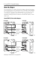
ArmorPOINT I/O DeviceNet Adapters About the Adapter The ArmorPOINT I/O family of DeviceNet adapters ship with the adapter and a terminating base to be used with the last I/O module on the backplane. The sealed IP67 housing of these adapters requires no enclosure. Note that environmental requirements other than IP67 may require an additional appropriate housing. DeviceNet connectors are sealed M12 (micro) or M18 (mini) styles.
ArmorPOINT I/O DeviceNet Adapters 5 Mount the I/O Base Mount the I/O base on a wall or panel, use the screw holes provided in the adapter. IMPORTANT ATTENTION ATTENTION The ArmorPOINT I/O module must be mounted on a grounded metal mounting plate or other conductive surface. To comply with the CE Low Voltage Directive (LVD), all connected I/O must be powered from a source compliant with the following: Safety Extra Low Voltage (SELV) or Protected Extra Low Voltage (PELV).
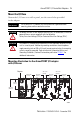
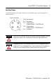
ArmorPOINT I/O DeviceNet Adapters Install the mounting as follows: 1. Lay out the required points as shown in the drilling dimension drawing. 2. Drill the necessary holes for M4 (#8) machine or self-tapping screws. 3. Mount the base using M4 (#8) screws. 4. Ground the system using the ground lug connection. The ground lug connection is also a mounting hole. Mounting Base Keyswitch Ground lug connection Latching mechanism 43675 Install the Adapter Follow the instructions to install the adapter. 1.
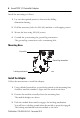
ArmorPOINT I/O DeviceNet Adapters 7 Remove the Adapter From the Mounting Base Follow the instructions to remove the adapter from the mounting base. 1. Put a flat blade screwdriver into the slot of the orange latching mechanism. 2. Push the screwdriver toward the I/O module to disengage the latch. The module lifts up off the base. 3. Pull the module off the base. Set the Network Address Valid node addresses are 00…63.
ArmorPOINT I/O DeviceNet Adapters minor fault occurs, which is indicated by a flashing red Adapter Status LED. Settings of 64…99 cause the module to use the last valid node address stored internally. Example: The last setting internally was 40. If a change is made to 68, and then you power up, the address will default to 40. The module is equipped with AutoBaud detect. AutoBaud lets the module read the settings already in use on your DeviceNet network and automatically adjusts to follow those settings.
ArmorPOINT I/O DeviceNet Adapters 9 Auxiliary Power Attach the mini-style 4-pin connector to the mini-style 4-pin receptacle as shown below. Male in Connector 43587 ATTENTION ATTENTION (View into connector) Pin 1 User power+ Pin 2 Adapter power+ Adapter/Subnet+ (1738-ADNX only) Pin 3 Adapter powerAdapter/Subnet- (1738-ADNX only) Pin 4 User power- Make sure all connectors and caps are securely tightened to properly seal the connections against leaks and maintain IP enclosure type requirements.
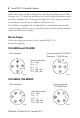
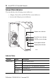
ArmorPOINT I/O DeviceNet Adapters Interpret Status Indicators This module has the following status indicators: • Adapter, DeviceNet and POINTBus status indicators • System and Adapter power indicators 1738-ADN18 DeviceNet Adapter status indicator Adapter Status X1 X10 DeviceNet Status PointBus Status System Power Adapter Power PWR DeviceNet status indicator POINTBus status indicators System power indicator Adapter power indicator 43783 Indicator Status Indicator Status Description Adapter
ArmorPOINT I/O DeviceNet Adapters 11 Indicator Status Indicator Status Description DeviceNet status Off Device is not online: - Device attempting to AutoBaud - Device has not completed dup_MAC-ID test - Device not powered – check adapter status indicator. POINTBus status POINTBus status (1738-ADNX only) Flashing green Device is online but has no connections in the established state. Green The device is online and has connections in the established state.
ArmorPOINT I/O DeviceNet Adapters Indicator Status Indicator Status Description System power Off Not active – field power is off or DC-DC converter problem. Green System power on – DC-DC converter active (5V). Adapter power Off Not active – field power is off. Green Power on, 24V present.
ArmorPOINT I/O DeviceNet Adapters 13 Specifications Attributes Value Expansion I/O capacity 63 modules max. Actual number of modules can vary. Add up current requirements of modules you want to use to make sure they do not exceed the amperage limit of 1.0 A for the ArmorPOINT I/O DeviceNet adapter. Backplane current can be extended beyond 1.0 A with a 1738-EP24DC Backplane Extension Power Supply. The 1738-EP24DC can supply up to an additional 1.3 A of backplane current.
ArmorPOINT I/O DeviceNet Adapters Power Supply Specifications Attributes Value Input voltage rating, nom 24V DC Input voltage range 10…28.8V DC Input overvoltage protection Reverse polarity protected Inrush current 6 A max for 10 ms POINTBus output current, max 1 A @ 5V DC ±5% (4.75…5.25) Field side power requirements, max 24V DC (+20% = 28.
ArmorPOINT I/O DeviceNet Adapters 15 General Specifications Mounting base screw torque M4 (#8) screw 0.86 Nm (7.5 lb-in) in Aluminum 1.81 Nm (16 lb-in) in Steel Wiring category(1) 1 – on power ports 1 – on communications ports (1) Use this Conductor Category information for planning conductor routing. Refer to publication 1770-4.1, Industrial Automation Wiring and Grounding Guidelines.
Environmental Specifications Attribute Value EFT/B immunity IEC 61000-4-4: ±4 kV @ 5 kHz on power ports ±3 kV @ 5 kHz on communications ports Surge transient immunity IEC 61000-4-5: ±1 kV line-line(DM) and ±2 kV line-earth(CM) on power ports ±2 kV line-earth(CM) on communications ports Conducted RF immunity IEC 61000-4-6: 10V rms with 1 kHz sine-wave 80% AM from 150 kHz…80 MHz Certifications Certification Value (when product is marked)(1) CE European Union 2004/108/EU EMC Directive, compliant wit