Installation Instructions ArmorPoint I/O Modules with 8 Configurable 24V DC Points and DeviceLogix Catalog Number(s) 1738-8CFGDLXM8, 1738-8CFGDLXM12, 1738-8CFGDLXM23 Topic Page Important User Information 2 Environment and Enclosure 3 Prevent Electrostatic Discharge 3 About the Module 4 Mount the I/O Base 5 Install the Digital Module 6 Remove the Module From the Mounting Base 7 Wire the Module 8 Communicate with Your Module 9 Interpret the Status Indicators 16 Specifications 18
ArmorPoint I/O Modules with 8 Configurable 24V DC Points and DeviceLogix Important User Information Solid state equipment has operational characteristics differing from those of electromechanical equipment. Safety Guidelines for the Application, Installation and Maintenance of Solid State Controls (Publication SGI-1.1 available from your local Rockwell Automation sales office or online at http://literature.rockwellautomation.
ArmorPoint I/O Modules with 8 Configurable 24V DC Points and DeviceLogix 3 Environment and Enclosure ATTENTION This equipment is intended for use in overvoltage Category II applications (as defined in IEC 60664-1), at altitudes up to 2000 m (6562 ft) without derating. This equipment is considered Group 1, Class A industrial equipment according to IEC/CISPR 11.
ArmorPoint I/O Modules with 8 Configurable 24V DC Points and DeviceLogix About the Module The ArmorPoint I/O family consists of modular I/O modules. The sealed IP67 housing of these modules requires no enclosure. Note that environmental requirements other than IP67 may require an additional appropriate housing. I/O connectors are sealed M8 (pico), M12 (micro) or M23 styles. The mounting base ships with the module.
ArmorPoint I/O Modules with 8 Configurable 24V DC Points and DeviceLogix 5 Mount the I/O Base Mount the I/O base on a wall or panel, using the screw holes provided in the base. The ArmorPoint I/O module must be mounted on a grounded metal mounting plate or other conductive surface. IMPORTANT ATTENTION ATTENTION Make sure all connectors and caps are securely tightened to properly seal the connections against leaks and maintain IP enclosure type requirements.
ArmorPoint I/O Modules with 8 Configurable 24V DC Points and DeviceLogix Install the mounting as follows: 1. Lay out the required points as shown above in the drilling dimension drawing. 2. Drill the necessary holes for M4 (#8) machine or self-tapping screws. 3. Mount the base using M4 (#8) screws. 4. Ground the system using the ground lug connection. The ground lug connection is also a mounting hole.
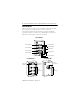
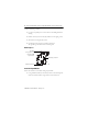
ArmorPoint I/O Modules with 8 Configurable 24V DC Points and DeviceLogix 7 2. Position the module vertically above the mounting base. The module bridges two bases. 1738-8CFGDLXM12 shown Module bridges two bases A DLX B H 1738-8CFGDLXM12 24V DC G MOD NET 0 1 2 C F 3 4 5 D E 6 7 44930 3. Push the module down until it engages the latching mechanism. You will hear a clicking sound when the module is properly engaged. The locking mechanism locks the module to the base.
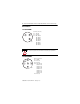
ArmorPoint I/O Modules with 8 Configurable 24V DC Points and DeviceLogix Wire the Module 1738-8CFGDLXM8 43583 ATTENTION (view into connector) Pin 1 - 24V DC Pin 3 - Common Pin 4 - I/O 0 (M8-A) I/O 1 (M8-B) I/O 2 (M8-C) I/O 3 (M8-D) I/O 4 (M8-E) I/O 5 (M8-F) I/O 6 (M8-G) I/O 7 (M8-H) Make sure all connectors and caps are securely tightened to properly seal the connections against leaks and maintain IP enclosure type requirements.
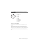
ArmorPoint I/O Modules with 8 Configurable 24V DC Points and DeviceLogix 9 1738-8CFGDLXM23 1 8 9 7 2 10 12 6 3 11 4 5 43681 (view into connector) Pin 1 - I/O 0 Pin 2 - I/O 1 Pin 3 - I/O 2 Pin 4 - I/O 3 Pin 5 - I/O 4 Pin 6 - I/O 5 Pin 7 - I/O 6 Pin 8 - I/O 7 Pin 9 - Return (Com) Pin 10 - Return (Com) Pin 11 - 24V DC Pin 12 - Chassis Communicate with Your Module Read this section for information about how to communicate with your module.
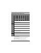
ArmorPoint I/O Modules with 8 Configurable 24V DC Points and DeviceLogix Default Data Map - Produced Assembly Instance 101 Message Size: 20 Bytes Bit 7 6 5 Data [0] Pt 07 PT 06 Pt 05 Data [1] PNB 07 PNB 06 PNB 05 Data [2] Reserved PM 6 PM 5 Data [3] Data [4] PM 7 4 3 Pt 04 Pt 03 PNB 04 PNB 03 PM 4 PM 3 2 1 0 Pt 02 Pt 01 Pt 00 PNB 02 PNB 01 PNB 00 Owned LogicEn PM 1 PM 0 PM 2 Produced Network Analog Word 0 Data [5] Data [6] Produced Network Analog Word 1 Data [7] D
ArmorPoint I/O Modules with 8 Configurable 24V DC Points and DeviceLogix 11 You can select other produced assemblies: • Produced assembly instance 4 is the first byte of produced assembly instance 101 (Data [0]). • Produced assembly instance 111 is the first eight bytes of produced assembly instance 101 (Data [0]…[7]). In RSLogix5000, the default tags will be: • • • • • • AdapterName:SlotNumber:I.Data AdapterName:SlotNumber:I.LogicDefinedData AdapterName:SlotNumber:I.Status.
ArmorPoint I/O Modules with 8 Configurable 24V DC Points and DeviceLogix Default Data Map - Consumed Assembly Instance 102 Data [12] Consume Network Analog Word 4 Data [13] Data [14] Consume Network Analog Word 5 Data [15] Data [16] Consume Network Analog Word 6 Data [17] Data [18] Consume Network Analog Word 7 Data [19] Where: Pt = state of the input point CNB = Consume Network Bit You can select other consumed assemblies: • Consumed assembly instance 34 is the first byte of consumed assembly
ArmorPoint I/O Modules with 8 Configurable 24V DC Points and DeviceLogix 13 Data Map - Configuration Assembly 123 Data [4] FltM 7 FltM 6 FltM 5 FltM 4 FltM 3 FltM 2 FltM 1 FltM 0 Data [5] FltV 7 FltV 6 FltV 5 FltV 4 FltV 3 FltV 2 FltV 1 FltV 0 Data [6] IdIM 7 IdIM 6 IdIM 5 IdIM 4 IdIM 3 IdIM 2 IdIM 1 IdIM 0 Data [7] IdIV 7 IdIV 6 IdIV 5 IdIV 4 IdIV 3 IdIV 2 IdIV 1 IdIV 0 Data [8] Reserved RACK CFO DM MP Data [9] Reserved Data [10] Masterless Produce Assembly Inst
ArmorPoint I/O Modules with 8 Configurable 24V DC Points and DeviceLogix Data Map - Configuration Assembly 123 Data [30] Peer 3 - EPR (ms) Data [31] Data [32] Peer 4 - Slot/MacID Data [33] Peer 4 - Consume Message Length (bytes) Data [34] Peer 4 - EPR (ms) Data [35] Data [36] Peer 5 - Slot/MacID Data [37] Peer 5 - Consume Message Length (bytes) Data [38] Peer 5 - EPR (ms) Data [39] Data [40] Peer 6 - Slot/MacID Data [41] Peer 6 - Consume Message Length (bytes) Data [42] Peer 6 - EPR (m
ArmorPoint I/O Modules with 8 Configurable 24V DC Points and DeviceLogix 15 Data Map - Configuration Assembly 123 Data [46] Peer 7 – EPR (ms) Data [47] Where: Filter = 0...
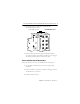
ArmorPoint I/O Modules with 8 Configurable 24V DC Points and DeviceLogix Interpret the Status Indicators 1738-8CFGDLXM8 shown 1738-8CFGDLXM8 24V DC 0 1 Module / Network Status Indicator MOD 2 NET 3 0 1 4 5 DeviceLogix Status Indicator 2 3 I/O Status Indicators 4 6 7 5 6 7 44931 1738-8CFGDLXM8, 1738-8CFGDLXM12, 1738-8CFGDLXM23 Indicator Status Mod/Net status Status Description Off No power applied to device or device is auto bauding. Green Device operating normally.
ArmorPoint I/O Modules with 8 Configurable 24V DC Points and DeviceLogix 17 1738-8CFGDLXM8, 1738-8CFGDLXM12, 1738-8CFGDLXM23 Indicator Status Network status I/O status Status Description Off Device is not online: - Device has not completed dup_MAC-id test. - Device not powered – check module status indicator. Green Device is online and has one or more I/O connections in established state. Flashing green Device is online but has no connections in established state.
ArmorPoint I/O Modules with 8 Configurable 24V DC Points and DeviceLogix Specifications ArmorPoint Digital Module with Configurable 24V DC Points 1738-8CFGM8, 1738-8CFGM12, 1738-8CFGM23 Attribute Value Number of I/O 8 On-state voltage, min 11 V DC On-state current, min 2.0 mA On-state current, max 5.0 mA Off-state voltage, max 5V DC Off-state current, min 1.5 mA Input filter Each input independently settable in 1 ms intervals (truncated to 1 ms resolution). Default value is 1000 ms.
ArmorPoint I/O Modules with 8 Configurable 24V DC Points and DeviceLogix 19 General Specifications Attribute Value Dimensions (HxWxD), approx. 120 x 72 x 42 mm (4.72 x 2.83 x 4.25 in) Weight, approx. 290 g (10.24 oz) POINTBus current, max 100 mA @ 5V DC Power dissipation, max. 2.6 W @ 28.8V DC Thermal dissipation, max. 8.9 BTU/hr @ 28.
ArmorPoint I/O Modules with 8 Configurable 24V DC Points and DeviceLogix Environmental Specifications Attribute Value Temperature, operating IEC60068-2-1 (Test Ad, Operating Cold), IEC60068-2-2, (Test Bd, Operating Dry Heat), IEC 60068-2-14 (Test Nb, Operating Thermal Shock): -20...60 °C (-4...140 °F) Temperature, nonoperating IEC60068-2-1 (Test Ad, Non-operating Cold), IEC60068-2-2, (Test Bd, Non-operating Dry Heat), -40...85 °C (-40...
ArmorPoint I/O Modules with 8 Configurable 24V DC Points and DeviceLogix 21 Certifications Certification (when Value product is marked)(1) CE European Union 2004/108/EC EMC Directive, compliant with: EN 61326-1; Meas./Control/Lab.
ArmorPoint I/O Modules with 8 Configurable 24V DC Points and DeviceLogix Notes: Publication 1738-IN027B-EN-E - February 2010
ArmorPoint I/O Modules with 8 Configurable 24V DC Points and DeviceLogix 23 Notes: Publication 1738-IN027B-EN-E - February 2010
Rockwell Automation Support Rockwell Automation provides technical information on the Web to assist you in using its products. At http://support.rockwellautomation.com, you can find technical manuals, a knowledge base of FAQs, technical and application notes, sample code and links to software service packs, and a MySupport feature that you can customize to make the best use of these tools.