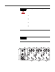
Installation Instructions ArmorPoint I/O RS-485 ASCII Module, Series A (Cat. No. 1738-485ASCM12) The ArmorPoint I/O family (Cat. no. 1738) consists of modular I/O modules. The sealed IP67 housing of these modules requires no enclosure. (Note that environmental requirements other than IP67 may require an additional appropriate housing.) The I/O connector is a sealed M12 (micro) style. The mounting base ships with the module. The 1738-485ASCM12 module is shown below.
ArmorPoint I/O RS-485 ASCII Module, Series A Important User Information Solid state equipment has operational characteristics differing from those of electromechanical equipment. Safety Guidelines for the Application, Installation and Maintenance of Solid State Controls (Publication SGI-1.1 available from your local Rockwell Automation sales office or online at http://www.ab.com/manuals/gi) describes some important differences between solid state equipment and hard-wired electromechanical devices.
ArmorPoint I/O RS-485 ASCII Module, Series A ATTENTION 3 Environment and Enclosure This equipment is intended for use in overvoltage Category II applications (as defined in IEC publication 60664-1), at altitudes up to 2000 meters without derating. This equipment is considered Group 1, Class A industrial equipment according to IEC/CISPR Publication 11.
ArmorPoint I/O RS-485 ASCII Module, Series A Preventing Electrostatic Discharge ATTENTION This equipment is sensitive to electrostatic discharge, which can cause internal damage and affect normal operation. Follow these guidelines when you handle this equipment: • Touch a grounded object to discharge potential static. • Wear an approved grounding wriststrap. • Do not touch connectors or pins on component boards. • Do not touch circuit components inside the equipment.
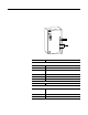
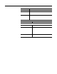
ArmorPoint I/O RS-485 ASCII Module, Series A 5 Install the mounting base as follows: 1. Lay out the required points as shown above in the drilling dimension drawing. 2. Drill the necessary holes for #8 (M4) machine or self-tapping screws. 3. Mount the base using #8 (M4) screws. 4. Ground the system using the ground lug connection. (The ground lug connection is also a mounting hole.
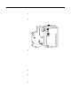
ArmorPoint I/O RS-485 ASCII Module, Series A Install the ArmorPoint RS-485 ASCII Module To install the ArmorPoint RS-485 ASCII module, proceed as follows. 1. Using a bladed screwdriver, rotate the keyswitch on the mounting base clockwise until the number 2 aligns with the notch in the base. 2. Position the module vertically above the mounting base. The module will bridge two bases. Module will bridge two bases. 1738-485ASCM12/A ASCII Interface MOD NET TxD RxD 43802 3.
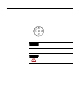
ArmorPoint I/O RS-485 ASCII Module, Series A Wire the RS-485 ASCII Modules 7 Following are wiring instructions for the ArmorPoint RS-485 ASCII module. 1738-485ASCM12 (view into connector) Pin 1 - Tx Pin 2 - Tx + Pin 3 - Rx + Pin 4 - Rx Pin 5 - No Connect 43664 IMPORTANT ATTENTION The 1738-485ASCM12 module has earth grounded metal rings. This should be considered when choosing shielded cables and grounding techniques.
ArmorPoint I/O RS-485 ASCII Module, Series A Communicate With Your Module The ASCII module operates as the PointBus front-end to your serial device. Data can be exchanged with the master through a polled, cyclic, or change of state connection. The module produces and consumes 4 to 132 bytes of data.
ArmorPoint I/O RS-485 ASCII Module, Series A Indication Probable Cause Flashing Red One or more I/O connections in timed-out state. Red Critical link failure - failed communication device. Device detected error that prevents it from communicating on the network. Flashing Red/Green Communication faulted device - the device has detected a network access error and is in communication faulted state. Device has received and accepted an Identity Communication Faulted Request - long protocol message.
ArmorPoint I/O RS-485 ASCII Module, Series A Specifications ArmorPoint 1738-485ASCM12 Module Inputs per Module Input Voltage Following are specifications for the 1738 ArmorPoint ASCII module. 1 full duplex Threshold Voltages Signal A with respect to Signal B Some RS-422 and RS-485 equipment use “+” and “-” descriptors. The “-” corresponds to “A” and the RS-422 RS-485 “+” corresponds to “B”. +2 to +6V dc (Transmitter) +1.5 to +6V dc (Transmitter) +0.2 to +7V dc (Receiver) +0.
ArmorPoint I/O RS-485 ASCII Module, Series A Send (Produce) on DeviceNet to Master Receive String Data Type Pad Mode Pad Character Receive Swap Mode DeviceNet Handshake Mode Produce Assembly Size Serial Data Receive Transaction ID Serial Port Transmit to ASCII Device Maximum Number of Transmit Characters Transmit End Delimiter Mode Transmit End Delimiter Character Consume on DeviceNet from Master Consume String Data Type Transmit Swap Mode DeviceNet Record Header Mode Consume Assembly Size Serial Port Tran
ArmorPoint I/O RS-485 ASCII Module, Series A General Specifications (continued) Surge Transient Immunity Conducted RF Immunity Emissions Enclosure Type Rating Mounting Base Screw Torque Wiring Category1 Weight Imperial (Metric) Certifications: (when product is marked) IEC 61000-4-5: ±2kV line-earth(CM) on shielded ports IEC 61000-4-6: 10Vrms with 1kHz sine-wave 80%AM from 150kHz to 80MHz CSPR 11: Group 1, Class A Meets IP65/66/67 (when marked) #8 screw, 7.5 in. lbs. in Aluminum, 16 in. lbs.
ArmorPoint I/O RS-485 ASCII Module, Series A 13 ArmorPoint is a trademark of Rockwell Automation. DeviceNet is a trademark of Open DeviceNet Vendor Association.
Rockwell Automation Support Rockwell Automation provides technical information on the web to assist you in using our products. At http://support.rockwellautomation.com, you can find technical manuals, a knowledge base of FAQs, technical and application notes, sample code and links to software service packs, and a MySupport feature that you can customize to make the best use of these tools.