
User Manual Owner's manual

Rockwell Automation Publication PROCES-UM002A-EN-P - July 2014 99
Prowirl 73 Flowmeter Appendix D
Signals from Instrument to Control System
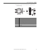
Connect a Prowirl 73
Flowmeter
Use a 2-wire connection to the HART input module.
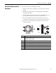
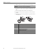
1. Unscrew the cover (a) of the electronics compartment from the
transmitter housing.
2. Remove the display module (b) from the retaining rails (c) and refit onto
right retaining rail with the left side (this secures the display module).
3. Loosen screw (d) of the cover of the connection compartment and fold
down the cover.
4. Push the cable for the power supply/current output through the cable
gland (e).
Optional: Push the cable for the pulse output through the cable gland (f ).
5. Tighten the cable glands (e/f ).
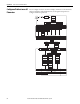
6. Pull the terminal connector (g) out of the transmitter housing and
connect the cable for the power supply/current output (see wiring
diagram).
Optional: Pull terminal connector (h) out of the transmitter housing and
connect the cable for the pulse output (see wiring diagram).
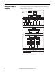
Signal Details
Current Output • 4 to 20 mA with HART
• Full scale value and time constant (0 to 100 s) can be set
Frequency Output, Pulse/Status Output Frequency output (optional): open collector, passive, galvanically isolated
• Non-Ex, Ex d/XP version:
– U
max = 36 V, with 15 mA current limiting, Ri = 500 Ω
• Ex i/IS and Ex n version:
– Umax = 30 V, with 15 mA current limiting, Ri = 500 Ω
Frequency output:
• End frequency 0 to 1000 Hz (fmax = 1250 Hz)
Pulse output:
• Pulse value and polarity can be selected (5 to 2000 ms)
• Pulse width can be configured (0.005 to 2 s)
• Pulse frequency max. 100 Hz
Status output:
• Can be configured for error messages or flow values, temperature values, pressure limit values
Vortex frequency:
• Direct output of unscaled vortex pulses 0.5 to 2850 Hz (e.g. for connecting to an RMC621 flow computer)
• Pulse ratio 1:1
IMPORTANT
The terminal connectors (g/h) are pluggable, i.e. they can be plugged out of
the transmitter housing to connect the cables.