
User Manual Owner's manual

Rockwell Automation Publication PROCES-UM002A-EN-P - July 2014 91
Proline t-mass 65 Thermal Flowmeter Appendix B
Connect a Proline t-mass 65
Flowmeter
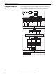
Use a 4-wire connection to the HART input module.
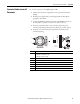
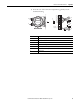
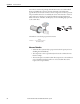
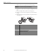
1. Unscrew the connection compartment cover (f ) from the transmitter
housing.
2. Feed the power supply cable (a) and the signal cable (b) through the
appropriate cable entries.
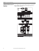
3. Connect the HART communications cable to the HART connector in
the order white (+), black (-) on pins 26, 27 of the connector.
4. For AC powered instruments, connect the AC cable to the power
connector in the order ground (as shown), black (pin 1), white (pin 2).
5. Screw the cover of the connection compartment (f ) back onto the
transmitter housing.
Item Description
a Cable for power supply: 85...260 V AC, 20...55 V AC, 16...62 V DC
• Terminal No. 1: L1 for AC, L+ for DC
• Terminal No. 2: N for AC, L- for DC
b Signal cable: Terminals Nos. 20-27
c Ground terminal for protective earth
d Ground terminal for signal cable shield
e Service adapter for connecting service interface FXA193 (FieldCheck, FieldCare)
f Cover of the connection compartment
g Securing clamp
b
b
c
d
a
a
2
1
–27
–25
–23
–21
+26
+24
+22
+20
L1 (L+)
N (L-)
g
f
e