
User Manual Owner's manual

Rockwell Automation Publication PROCES-UM002A-EN-P - July 2014 85
Promag 53 Electromagnetic Flowmeter Appendix A
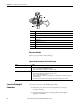
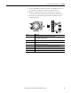
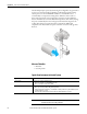
3. Connect the HART communications cable to the HART connector in
the order white (+), black (-) on pins 26, 27 of the connector.
4. For AC powered instruments, connect the AC cable to the power
connector in the order ground (as shown), black (pin1), white (pin2).
5. Screw the cover of the connection compartment (f ) firmly onto the
transmitter housing.
Item Description
a Cable for power supply: 85...260 V AC, 20...55 V AC, 16...62 V DC
• Terminal No. 1: L1 for AC, L+ for DC
• Terminal No. 2: N for AC, L- for DC
b Signal cable: Terminal Nos. 20-27
c Ground terminal for protective conductor
d Ground terminal for signal cable shield
e Service adapter for connecting service interface FXA 193 (FieldCheck, FieldCare)
f Cover of the connection compartment
gSecuring clamp
b
b
c
d
a
a
2
1
–27
–25
–23
–21
+26
+24
+22
+20
L1 (L+)
N (L-)
g
f
e