
User Manual Owner's manual

84 Rockwell Automation Publication PROCES-UM002A-EN-P - July 2014
Appendix A Promag 53 Electromagnetic Flowmeter
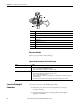
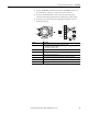
Measured Variable
Flow rate (proportional to induced voltage)
Signals from Instrument to Control System
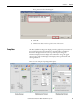
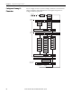
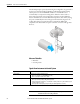
Connect a Promag 53
Flowmeter
Use a 4-wire connection to the HART input module.
1. Remove the cover of the connection compartment (f ) from the
transmitter housing.
2. Feed the power supply cable (a) and signal cables (b) through the
appropriate cable entries.
Item Description
Ue Induced voltage, Ue = B· L· v
B Magnetic induction (magnetic field)
LElectrode gap
VFlow velocity
Q Volume flow,
Q = A· v
A Pipe cross-section
I Current strength
Signal Details
Current Output Active/passive selectable, galvanically isolated
• Active: 0/4...20 mA, RL < 700 Ω (HART: RL ≥ 250 Ω)
• Passive: 4...20 mA, operating voltage VS 18...30V DC, Ri <
150 Ω
Pulse/Frequency Output Active/passive selectable, galvanically isolated (Ex i version: only passive)
• Active: 24 V DC, 25 mA (max. 250 mA during 20 ms), RL > 100 Ω
• Passive: open collector, 30V DC, 250 mA
• Frequency output: full scale frequency 2...10000 Hz (fmax = 12500 Hz), EEx-ia: 2...5000 Hz; on/off ratio 1:1;
pulse width max. 10 s
• Pulse output: pulse value and pulse polarity adjustable, pulse width configurable (0.05...2000 ms)