
User Manual Owner's manual


Rockwell Automation Publication PROCES-UM002A-EN-P - July 2014 15
Installation Chapter 1
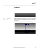
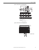
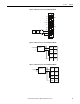
Figure 3 - 2-Wire Connection to 1794-IE8H Input Module
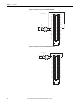
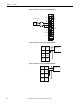
Figure 4 - 2-Wire Connection to 1794-IF8IH Input Module
17 18 19 20 21 22 23 24 25 26 27 28 29 30 31 32 33
0 1 2 3 4 5 6 7 8 9 10 11 12 13 14 15
16
35 36 37 38 39 40 41 42 43 44 45 46 47 48 49 50 51
34
Chassis
Ground
(1794-TB3G shown)
Chassis
Ground
+V -V (COM)
24C dc
Supply In
+V -V (COM)
24C dc
Supply Out
Chassis Grounds for Shields
+V = +24V dc = Terminals C-34 and C-50
-V = COM = C-35 and C-51
Chassis Ground = Terminals B-16, B-33, C-38, C-40…45, and C-47
A
B
C
For daisy-chaining: Supply in - C-34 (+) and C-35 (-)
Supply out - C-50 (+) and C-51 (-)
NC = No connection
CNCN
+
_
+
_
+
_
+
_
+
_
+
_
+
_
+
_
3hC1hC0hC
Ch5
Ch2
7hC6hC4hC
Flexbus
Bus
uC
+V
-V
+
Sig
-
4 to 20mA
Xmit
4 to 20mA
Xmit
I
P
P
I
40072
22 Ω
91 Ω
17V
0 1 2 3 4 5 6 7 8 9 10 11 12 13 14 15
33322212029181 24 2526 2728 2930 313217
059484748373635334
51
16
39 40 41 42 43 44 45 46
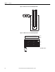
Row A
Row B
Row C
Row B
Row C
Row A
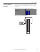
1794-TB3S shown
Label placed at top of wiring area
Current
input