
User Manual Owner's manual


144 Rockwell Automation Publication PROCES-UM002A-EN-P - July 2014
Appendix L iTEMP TMT182 Temperature Transmitter
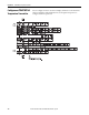
Signals from Instrument to Control System
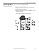
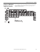
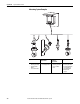
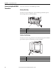
Connect an iTEMP TMT182
Temperature Transmitter
Use a 2-wire connection to the HART input module.
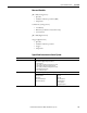
Signal Details
Output Signal Analog 4...20mA, 20...4mA
Load Max. (VPower supply - 11.5 V) / 0.022 A (current output)
Switch on Delay 4 s (during power up la - 3.8 mA)
Galvanic Isolation U = 2 kV AC (input/output)
Signal on Alarm • Underranging:
Linear drop to 3.8 mA
• Overranging:
Linear rise to 20.5 mA
• Sensor break; sensor short-circuit (not for thermocouples TC):
3.6 mA or 21.0 mA
Failure signal 21.0 mA; if output setting is 21.0 mA,
> 21.5 mA is guaranteed
Allowable Ripple Uss ≤ 3 V at Ub ≥ 13 V, fmax. = 1 kHz