
User Manual Owner's manual


Rockwell Automation Publication PROCES-UM002A-EN-P - July 2014 135
Prosonic S Transmitter Appendix J
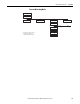
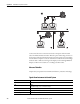
Signals from Instrument to Control System
Connect a Prosonic S
Transmitter
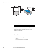
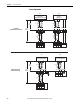
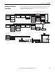
Use a 4-wire connection to the HART input module. Following are the terminals
of the Prosonic S. The terminals depicted in grey are not present in every
instrument version.
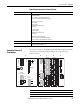
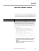
Output Signal Details
Current Output 4...20 mA with HART
0...20mA without HART
USS = 200 mV at 47...125Hz (measured at 500Ω)
Ueff = 2,2 mV at 500 Hz... 10 kHz (measured at 500Ω)
For Setting 4...20 mA, selectable
• 10% (3,6 mA)
• 110% (22 mA)
• HOLD (last current value is held)
• User specific
For Setting 0...20 mA
• 110% (21,6 mA)
• HOLD (last current value is held)
• User specific
Maximum 600 Ω, influence negligible
• USS = 200 mV at 47...125Hz (measured at 500Ω)
• Ueff = 2,2 mV at 500 Hz...10kHz (measured at 500Ω)
Output Damping Freely selectable, 0...1000 s
Relay Outputs DC voltage: 35 VDC, 100 W
AC voltage: 4 A, 250 V, 100 VA at cos = 0.7
FDU-
Sensor
0/4...20mA
1
42
41
Relay
55
52
54
51
53
50
3
Address
Term.
DP
off
on
off
on
SW
HW
1
2
3
4
5
6
7
8
1
2
3
4
A(N)
66
B(P)
65
Display
POWER
HART
0/4…20mA
Sync
Fuse
I
1
FDU-
Sensor
RD
11
BK
10
YE
9
40
39
5
4
67
8
1
1
Service
Relay
32
1
A
B
C
E
2
58
5756
4
61
6059
5
64
6362
6
RD
11
BK
10
YE
9
2
RD
14
BK
13
YE
12
I
2
FDU-
Sensor
DigIn
76
73
75
72
74
71
2
D
1
79
7877
3
82
8180
4
85
8483
Temp.
Item Description
A Basic terminal area
B…E Optional terminal areas (present if the respective option has been selected in the product structure).