
User Manual Owner's manual


Rockwell Automation Publication PROCES-UM002A-EN-P - July 2014 117
Micropilot M Radar Level Appendix G
Connect a Micropilot M Level-
Radar
Use a 2-wire connection to the HART input module.
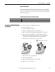
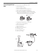
1. Unscrew housing cover (2).
2. Remove any display (3), if fitted.
3. Remove cover plate from terminal compartment (4).
4. Pull out terminal module slightly using pulling loop.
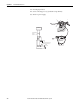
5. Insert cable (5) through gland (6). A standard installation cable is
sufficient if only the analog signal is used. Use a screened cable when
working with a superimposed communications signal (HART).
6. Only ground screening of the line (7) on sensor side.
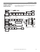
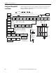
7. Make connection (see pin assignment).
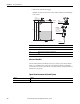
8. Re-insert terminal module.
9. Tighten cable gland (6).
10. Tighten screws on cover plate (4).
11. Insert display, if fitted.
12. Screw on housing cover (2).
13. Switch on power supply.
l
u
ky
l
z
zR
o
h
|
zl
y
l
u
k
y
lz
z
R
oh
|zly
2
3
Unplug displa
y connector!
!
12
3
4
4
5
7
6
3
4
I+
I-
1
2
L-
L+
4...20 mA
Sealed terminal
compartment
communication
resistor
(> 250 )Ω
plant
ground
test sockets
(output current)
power