
User Manual Owner's manual

100 Rockwell Automation Publication PROCES-UM002A-EN-P - July 2014
Appendix D Prowirl 73 Flowmeter
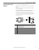
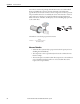
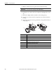
7. Plug the terminal connectors (g/h) into the transmitter housing.
8. Fold up the cover of the connection compartment and tighten the screws
(d).
9. Remove the display module (b) and fit on the retaining rails (c).
10. Screw the cover of the electronics compartment (a) onto the transmitter
housing.
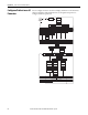
11. Only remote version: Secure the ground cable to the ground terminal (see
wiring diagram, c).
IMPORTANT
The connectors are coded so you cannot mix them up.
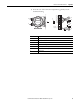
Item Description
a Cover of electronics compartment
b Display module
c Retaining rail for display module
d Connection compartment cover threaded connection
e Cable gland for power supply/current output cable
f Cable gland for pulse output cable (optional)
g Terminal connector for power supply/current output
h Terminal connector for pulse output (optional)
e
f
g
h
d
a
c
b
d