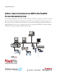
Integration Document Endress+Hauser Instruments via HART to the PlantPAx Process Automation System Systems with Analog I/O Modules: 1756-IF8H, 1756-IF8IH, 1756-IF16H, 1794-IF8IH, 1769sc-IF4IH, 1734sc-IE2CH, 1734sc-IE4CH Endress+Hauser Devices: Promag 53 Electromagnetic, Flowmeter, Proline T-mass 65 Thermal Flowmeter, Promass 83 Coriolis Mass Flowmeter, Prowirl 73 Flowmeter, Prosonic M Ultrasonic Level, Levelflex M Guided Radar Level, Micropilot M Radar Level, Deltabar S Differential Pressure, Prosonic S Tr
Important User Information Solid-state equipment has operational characteristics differing from those of electromechanical equipment. Safety Guidelines for the Application, Installation and Maintenance of Solid State Controls (publication SGI-1.1 available from your local Rockwell Automation® sales office or online at http://www.rockwellautomation.com/literature/) describes some important differences between solid-state equipment and hard-wired electromechanical devices.
Table of Contents Important User Information . . . . . . . . . . . . . . . . . . . . . . . . . . . . . . . . . . . . . . . . 2 Table of Contents Preface Preferred Integration . . . . . . . . . . . . . . . . . . . . . . . . . . . . . . . . . . . . . . . . . . . . . . . 7 Application Overview . . . . . . . . . . . . . . . . . . . . . . . . . . . . . . . . . . . . . . . . . . . . . . 8 Control System . . . . . . . . . . . . . . . . . . . . . . . . . . . . . . . . . . . . . . . . . . . . . .
Table of Contents Chapter 5 Visualization Add-On Instructions . . . . . . . . . . . . . . . . . . . . . . . . . . . . . . . . . . . . . . . . . . . . . Download the Add-On Instructions . . . . . . . . . . . . . . . . . . . . . . . . . . . Import Add-On Instructions . . . . . . . . . . . . . . . . . . . . . . . . . . . . . . . . . . Add an Add-On Instruction to a Routine. . . . . . . . . . . . . . . . . . . . . . . Configure I_AB56IF8H . . . . . . . . . . . . . . . . . . . . . . . . . . . . . . . . . . . .
Table of Contents Appendix E Prosonic M Ultrasonic Level Measured Variables . . . . . . . . . . . . . . . . . . . . . . . . . . . . . . . . . . . . . . . . . . Signals from Instrument to Control System. . . . . . . . . . . . . . . . . . . . Connect a Prosonic M Ultrasonic Level . . . . . . . . . . . . . . . . . . . . . . . . . . . Configure a Prosonic M Ultrasonic Level . . . . . . . . . . . . . . . . . . . . . . . . . 104 104 105 107 Appendix F Levelflex M Guided Radar Level Measured Variables . . . .
Table of Contents Appendix K iTEMP TMT162 Temperature Transmitter Measured Variables . . . . . . . . . . . . . . . . . . . . . . . . . . . . . . . . . . . . . . . . . . Signals from Instrument to Control System . . . . . . . . . . . . . . . . . . . . Connect an iTEMP TMT162 Temperature Transmitter . . . . . . . . . . . Configure an iTEMP TMT162 Temperature Transmitter. . . . . . . . . . 140 140 141 142 Appendix L iTEMP TMT182 Temperature Transmitter Measured Variables . . . . . . . . . . . . . . . . .
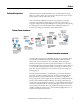
Preface Preferred Integration Rockwell Automation and Endress+Hauser have strengthened their strategic alliance to provide complete process automation solutions that use best-in-class instrumentation, software, and control systems. There are hundreds of different components in a typical plant: controllers, remote I/O, electrical drives, safety equipment, and sensors. Each must be integrated, configured and optimized during start-up and operation.
Preface The overall mission of the alliance is to provide you with proven solutions that combine field instrumentation with fieldbus networks, such as HART, FOUNDATION Fieldbus, and Profibus networks, with asset management capabilities and Rockwell Automation’s system capabilities to provide a total engineered solution.
Preface The tested HART devices are the following: • Promass 83 flowmeter • Promag 53 flowmeter • Proline t-mass 65 flowmeter • Prosonic S transmitter • Prowirl 73 flowmeter • Levelflex M guided level-radar • Micropilot M level-radar • Prosonic M ultrasonic level • Liquiline M CM42 transmitter • Cerabar S pressure transmitter • Deltabar S differential pressure • iTEMP TMT162 temperature transmitter • iTEMP TMT182 temperature transmitter The ControlLogix platform provides a full range of input and output mo
Preface Control System The control system includes these components: Component Description Controller The ControlLogix controller is a modular, high performance controller, that uses RSLogix 5000 programming software to configure, program, and monitor a system. The ControlLogix controller is certified by TUV for SIL 1 and SIL 2 applications. HART I/O module The HART analog I/O module converts to or from 4...20 mA analog signals and the digital values used in the controller.
Preface System Details These components and specifications are recommended for preferred integration.
Preface Performance Considerations Keep in mind these considerations when integrating HART instruments: • The HART communication protocol has a relatively slow baud rate at 1200/2400 bits per second. • The 1756-IF8H HART module executes one HART command per instrument at a time. Analog (4-20ma) data are delivered from all channels simultaneously. • The time of execution for Universal Command 3 is estimated from 200...600 ms, but varies based on the complexity and response time of the instrument.
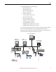
Chapter 1 Installation Connect a 2-Wire Field Instrument Topic Page Connect a 2-Wire Field Instrument 13 Connect a 4-Wire Field Instrument 17 HART communication is active only with current inputs. Connect a 2-wire field instrument to any channel of the HART input module in a 2-wire configuration for current input. HART devices that support 2-wire connections include the following.
Chapter 1 Installation Figure 1 - 2-Wire Connection to 1756-IF8H Input Module 2 Wire Current Input 2 Wire HART Device 24 VDC Power Supply +- + - IN0+ 2 1 I RTN-0 IN0- 4 3 NC IN1+ 6 5 I RTN-1 IN1- 8 7 NC RTN 10 9 RTN IN2+ 12 11 I RTN-2 IN2- 14 13 NC IN3+ 16 15 I RTN-3 IN3- 18 17 NC IN4+ 20 19 I RTN-4 IN4- 22 21 NC IN5+ 24 23 I RTN-5 IN5- 26 25 NC RTN 28 27 RTN IN6+ 30 29 I RTN-6 IN6- 32 31 NC IN7+ 34 33 I RTN-7 IN7- 36 35 NC Figure 2 - 2-Wire Co
Installation Chapter 1 Figure 3 - 2-Wire Connection to 1794-IE8H Input Module +V -V 91 Ω 17V Bus Flexbus 4 to 20mA Xmit 4 to 20mA Xmit + I uC I P P Sig 22 Ω 40072 0 1 2 3 4 5 Ch0 17 Chassis Ground 8 9 10 19 20 21 22 35 24 25 26 27 37 38 39 40 13 14 15 Ch3 28 29 30 31 32 42 43 44 45 33 B + _ Ch6 41 A + _ + _ Ch5 36 12 Ch2 23 + _ + _ 11 + _ Ch1 18 Ch4 34 7 + _ + _ 16 6 Chassis Ground Ch7 46 47 48 49 50 51 C +V -V (COM) NC 24C dc Su
Chapter 1 Installation Figure 5 - 2-Wire Connection to 1769sc-IF4IH Input Module Ch0+ N/C 2 Wire Current Input N/C Ch1+ 2 Wire XMTR + - +- 24V DC Power Supply Ch1-iRtn Ch1- Ch0-iRtn Ch0N/C Ch2+ Ch2-iRtn N/C Ch3+ Ch2- Ch3-iRtn N/C Ch3- N/C Figure 6 - 2-Wire Connection to 1734sc-IE2CH Input Module 0 IN 0 1 IN 1 2 + 24 3 + 24 4 COM 5 COM 6 FGN 7 FGN 2 Wire Device Figure 7 - 2-Wire Connection to 1734sc-IE4CH Input Module 16 0 IN 0 1 IN 1 2 IN 2 3 IN 3 4 COM 5 + 24 6 FGN 7 FGN
Installation Connect a 4-Wire Field Instrument Chapter 1 HART communication is active only with current inputs. Connect a 4-wire field instrument to any channel of the HART input module in a 4-wire configuration for current input. HART devices that support 4-wire connections include the following.
Chapter 1 Installation Figure 9 - 4-Wire Connection to 1756-IF16H Input Module 4 Wire HART Device 24V DC Power Supply + + - + 4 Wire XMTR - - IN0+ 2 1 IN0- IN1+ 4 3 IN1- IN2+ 6 5 IN2- IN3+ 8 7 IN3- RTN 10 9 RTN IN4+ 12 11 IN4- IN5+ 14 13 IN5- IN6+ 16 15 IN6- IN7+ 18 17 IN7- IN8+ 20 19 IN8- IN9+ 22 21 IN9- IN10+ 24 23 IN10- IN11+ 26 25 IN11- RTN 28 27 RTN IN12+ 30 29 IN12- IN13+ 32 31 IN13- IN14+ 34 33 IN14- IN15+ 36 35 IN15- Figure 10 - 4-W
Installation Chapter 1 Figure 11 - 4-Wire Connection to 1769sc-IF4IH Input Module Ch0+ N/C Ch0-iRtn N/C Ch1+ Ch0N/C Ch1-iRtn Ch2+ Ch1- Ch2-iRtn N/C Ch3+ + +4 Wire+ XMTR - - - 24V DC Power Supply 4 Wire Current Input Ch2- Ch3-iRtn N/C Ch3- N/C Figure 12 - 4-Wire Connection to 1734sc-IE2CH Input Module AC/DC Pwr 4 Wire Device 0 IN 0 1 IN 1 2 + 24 3 + 24 4 COM 5 COM 6 FGN 7 FGN Figure 13 - 4-Wire Connection to 1734sc-IE4CH Input Module AC/DC Pwr 4 Wire Device 0 IN 0 1 IN 1 2
Chapter 1 Installation Notes: 20 Rockwell Automation Publication PROCES-UM002A-EN-P - July 2014
Chapter 2 Configure the HART Device in RSLogix 5000 Programming Software Topic Page Configure a HART Input Module in a ControlLogix System 21 Configure a HART Input Module in a Compact I/O System 27 Configure a HART Input Module in a FLEX I/O System 29 Configure a HART Input Module in a POINT I/O System 31 The examples in this chapter use RSLogix 5000 programming software, version 20.
Chapter 2 Configure the HART Device in RSLogix 5000 Programming Software To configure the I/O module, follow these steps within the configuration tree. 1. From the configuration tree, right click the 1756 backplane and choose New Module. If the controller communicates with the I/O module over a network, the network interfaces must be added to the configuration tree before adding the I/O module. 2. From the list, select the 1756-IF8H input module.
Configure the HART Device in RSLogix 5000 Programming Software Chapter 2 3. On the General tab, enter the configuration information for the module. 4. Click Change. 5. For Input Data, choose Analog and HART PV. 6. On the Configuration tab, enable HART for each channel connected to a device. Each channel must be enabled to pass HART data to the controller.
Chapter 2 Configure the HART Device in RSLogix 5000 Programming Software 7. On the Configuration tab, for Passthrough, choose Once per channel scanned. This passthrough selection is the fastest and best for asset management software. 8. When complete, click OK. 9. Click Download to go online.
Configure the HART Device in RSLogix 5000 Programming Software Chapter 2 10. From the HART Device Info tab in the HART module properties, verify that the instrument is connected.
Chapter 2 Configure the HART Device in RSLogix 5000 Programming Software 11. Check Controller Tags to verify that the HART instrument is connected and passing data. A connected instrument displays values in the PV, SV, TV, and FV fields. This tag example shows that the HART input module is in slot 6.
Configure the HART Device in RSLogix 5000 Programming Software Chapter 2 If HART data is not present, make sure the HART function is enabled. Configure a HART Input Module in a Compact I/O System Use RSWHO Active in RSLogix 5000 software to verify that the controller, HART input module, and devices are active. This example has a 1769-L35E CompactLogix controller and the Spectrum 1769sc-IF4IH module and uses the Spectrum sample ACD file.
Chapter 2 Configure the HART Device in RSLogix 5000 Programming Software The Spectrum 1769sc-IF4IH is configured as shown. Make sure that Enable Channel and Enable HART Communication are both checked. The Spectrum 1769sc-IF4IH has these controller tags.
Configure the HART Device in RSLogix 5000 Programming Software Chapter 2 This example shows the PV values from the device mapped to the data structure. Configure a HART Input Module in a FLEX I/O System In RSLogix 5000 software, you must have a project open with a controller already configured. Make sure the project path is set to the correct controller. Use RSWHO Active in RSLogix 5000 software to verify that the controller, HART input module, and devices are active.
Chapter 2 Configure the HART Device in RSLogix 5000 Programming Software 3. Enter the configuration information for the module and choose the HART communication format. 4. Click OK. 5. Go online and check the controller tags to make sure the device is connected.
Configure the HART Device in RSLogix 5000 Programming Software Configure a HART Input Module in a POINT I/O System Chapter 2 In RSLogix 5000 software, you must have a project open with a controller already configured. Make sure the project path is set to the correct controller. Use RSWHO Active in RSLogix 5000 software to verify that the controller, HART input module, and devices are active. To configure the I/O module, follow these steps within the configuration tree.
Chapter 2 Configure the HART Device in RSLogix 5000 Programming Software 2. From the list, select the HART input module and click Create. 3. Enter the configuration information for the module and click Change. 4. Enter additional configuration information and click OK. 5. From the Channel Configuration tab, choose the channel.
Configure the HART Device in RSLogix 5000 Programming Software Chapter 2 6. Enable the HART function for each channel required. 7. Click OK. 8. Go Online and check the controller tags to verify operation.
Chapter 2 Configure the HART Device in RSLogix 5000 Programming Software Notes: 34 Rockwell Automation Publication PROCES-UM002A-EN-P - July 2014
Chapter 3 Configure the HART Device in FactoryTalk AssetCentre Software Topic Page Update the DTM Catalog 35 Configure the DTM Network Path 36 Configure a HART Device 44 Configure a FLEX I/O Module 50 FactoryTalk AssetCentre Software is a FDT-based, plant asset management software tool that you use to configure intelligent field instruments for Endress+Hauser.
Chapter 3 Configure the HART Device in FactoryTalk AssetCentre Software 3. Look through the catalog of installed DTMs and look for a green checkmark on the appropriate DTM. A yellow triangle indicates that the DTM is found but needs to be scanned. 4. If necessary, click Scan Now and then verify that the DTMs you installed exist in the catalog. 5. Close the DTM catalog. Configure the DTM Network Path The network path will vary based on your system.
Configure the HART Device in FactoryTalk AssetCentre Software Chapter 3 2. Click on the name of the Host PC network on the tree to the left and then click Add DTM. 3. Click on the 1756 Chassis DTM.
Chapter 3 Configure the HART Device in FactoryTalk AssetCentre Software The tree should look like the following screen. 4. Select the chassis and click Add DTM The following screen should appear. 5. Browse to the backplane containing the appropriate controller. and click OK.
Configure the HART Device in FactoryTalk AssetCentre Software Chapter 3 6. Click Select path to autobrowse. For some I/O it may be necessary to click Open to configure the path. 7. Click Next. 8. Select DTM Networks and view the tree. 9. Select the chassis and click Add DTM.
Chapter 3 Configure the HART Device in FactoryTalk AssetCentre Software 10. Select the I/O module. 11. Click OK. 12. Enter the slot number and other configuration data.
Configure the HART Device in FactoryTalk AssetCentre Software Chapter 3 13. Click Next. 14. Select the module and click Add DTM.
Chapter 3 Configure the HART Device in FactoryTalk AssetCentre Software 15. Select the correct channel and click OK. Repeat for additional channels with devices. 16. Click Scan network to locate devices. 17. Click OK.
Configure the HART Device in FactoryTalk AssetCentre Software Chapter 3 18. Click DTM Info. 19. Make sure the correct DTMS are available and green. Scan for any required DTMS that appear in yellow.
Chapter 3 Configure the HART Device in FactoryTalk AssetCentre Software Configure a HART Device 1. Right click on the device an select Online. 2. Click Open. Device information should appear. 3. Click Next. 4. Click Design.
Configure the HART Device in FactoryTalk AssetCentre Software Chapter 3 5. Choose Process Area > New. 6. In the Process Area tree, select Instrument.
Chapter 3 Configure the HART Device in FactoryTalk AssetCentre Software 7. Enter the name of the device and click OK. 8. Right click on the name of the device you just created and select Properties.
Configure the HART Device in FactoryTalk AssetCentre Software Chapter 3 9. Select DTM Addressing Info and click on the ellipsis. 10. Select the device and click OK. The device information appears.
Chapter 3 Configure the HART Device in FactoryTalk AssetCentre Software 11. Click OK. 12. Right click on the device name and select DTM View.
Configure the HART Device in FactoryTalk AssetCentre Software Chapter 3 13. When the device information appears, go online. 14. Select any views desired and save the project.
Chapter 3 Configure the HART Device in FactoryTalk AssetCentre Software Configure a FLEX I/O Module 1. From the DTM Networks tree, select the FLEX rail. 2. Click Add DTM. 3. Select the FLEX I/O module and click OK. The tree should look similar to this.
Configure the HART Device in FactoryTalk AssetCentre Software Chapter 3 4. Select the FLEX rail. 5. Use AutoBrowse to select the path.
Chapter 3 Configure the HART Device in FactoryTalk AssetCentre Software Notes: 52 Rockwell Automation Publication PROCES-UM002A-EN-P - July 2014
Chapter 4 Configure the HART Device in E+H Fieldcare Software Topic Page Configure a HART Input Module and Device 53 Access Instrument Data 56 Additional Functions 58 FieldCare is the Endress+Hauser FDT-based, plant-asset management tool for configuring intelligent field instruments. Configure a HART Input Module and Device 1. Start FieldCare and open a new project. IMPORTANT To optimize FieldCare performance, it is recommended that you verify that the correct DTMs are loaded in the catalog.
Chapter 4 Configure the HART Device in E+H Fieldcare Software 2. Choose DTM Catalog > Update. 3. Select desired DTMs and click Move. If you do not find the desired DTMs, or if the left pane of the dialog box is empty, click Update. FieldCare software searches for DTMs installed on your computer. If necessary, to remove DTMs, select the desired DTMs in the right pane and click Move. 4. Click OK.
Configure the HART Device in E+H Fieldcare Software Chapter 4 5. From the Device Operation/Add Device menu, select the RSLinx 1756 Backplane and click OK. 6. To configure the RSLinx backplane, double-click on the RSLinx backplane in the left pane. 7. Click Select Path and drill down to the ControlLogix backplane.
Chapter 4 Configure the HART Device in E+H Fieldcare Software 8. From the Device Operation/Add Device menu, select the 1756-IF8H/A module and click OK. 9. To configure the 1756-IF8H module, double-click on the module backplane in the left pane. 10. Enter the slot number and click the Create Network icon. 11. When prompted, click OK. The Com DTM now scans the entire HART network behind the multiplexer and searches for the right DTM.
Configure the HART Device in E+H Fieldcare Software Chapter 4 3. In the Online pane, choose Device Data. 4. To view measured values, right-click on the instrument in the left pane and choose Observe.
Chapter 4 Configure the HART Device in E+H Fieldcare Software Additional Functions 58 You can use FieldCare software to perform these additional functions: • Toggle between connected and disconnected modes • Read from device • Write to device • Device-specific functions Rockwell Automation Publication PROCES-UM002A-EN-P - July 2014
Chapter 5 Visualization Topic Page Add-On Instructions 59 Global Object 75 Faceplates 81 To use the predesigned faceplates to monitor the instrument, HART must be enabled for the HART input module. FactoryTalk View SE faceplates provide for visualization of instruments connected to a HART input module. The HART input module provides the necessary data to the faceplates.
Chapter 5 Visualization Instruction becomes the link from the actual instrument to the faceplate on the graphic. Add-On Instruction Description I_AB56IF8H Structured input data for each HART 8 channel input module. The I_AB56IF8H Add-On Instruction collects and organizes data from module parameters and from a module query that provides extra HART data via a CIP message from the controller to the I/O module. I_AB56IF16H Structured input data for each HART 16 channel input module.
Visualization Chapter 5 Import Add-On Instructions To use the Add-On Instructions, you import them into a controller project. Follow these steps for each Add-On Instruction. 1. In the Controller Organizer window, right click on Add-On Instructions and choose Import Add-On Instruction.
Chapter 5 Visualization 2. Select the Add-On Instruction to import from the File Explorer window and click Import. 3. Click OK in the Import Configuration Window.
Visualization Chapter 5 4. Once the import is complete, the Add-On Instructions and any additiona data types are visible in the Controller Organizer. Add an Add-On Instruction to a Routine Follow these steps to add an Add-On Instruction to a routine. 1. Open the routine by double clicking the routine name in the Controller Organizer.
Chapter 5 Visualization 2. Right click in field of the sheet and select Add Element. 3. Browse to the Add-On Instruction folder, select the Add-On Instruction, and click OK. Repeat this process for each required Add-On Instruction. Each analog input module needs one I_AB56IF8H(for 8 channel) or I_AB56IF16H(for 16 channel), one I_AB56IFxH_Chan per HART device, and one P_AIn56H per device.
Visualization Chapter 5 When all the Add-On Instructions are in the routine, connect them as shown below. Each I_AB56IFxH_Chan connects to one of P_AIn56H. Configure I_AB56IF8H Make the following modifications to each I_AB56IF8H Add-On Instruction. • You must create the backing tag and all of the reference input tags. Follow a system or naming convention for your application to keep multiple instances of this Add-On Instruction organized.
Chapter 5 Visualization • Configure the Ref_ChanDevInfoMSG tag so the path points to the Analog HART Interface module in the chassis.
Visualization Chapter 5 • Configure the Ref_ModDiagMSG tag so the path points to the Analog HART Interface module in the chassis. Configure I_AB56IFxH_Chan Make the following modifications to the I_AB56IFxH_Chan Add-On Instruction. • You must create the backing tag. Follow a system or naming convention for your application to indicate the channel of the analog input module that it is referencing.
Chapter 5 Visualization • Configure Ref_ChanData and Ref_ChanDiag to point to the appropriate array channel position from the tags created in conjunction with I_AB56IF8H. Configure P_AIn56H Make the following modifications to the P_AIN56H Add-On Instruction. • You must create the backing tag. Follow a system or naming convention for your application to indicate the channel of the analog input module that it is referencing.
Visualization Chapter 5 • Configure the Ref_FaultTable and Ref_EUTable tags. These tables provide the fault codes and engineering units for the device. You can create your own table with device-specific codes and descriptions, or there are generic tables available in the sample projects contained within the PlantPAx Process Object Library.
Chapter 5 Visualization Link an Add-On Instruction to Graphics in FactoryTalk View SE Software This graphic displays how the P_AIn56H works within an HMI. • Pre-designed AOIs provide a two-way exchange of data between the faceplates and the ControlLogix controller.
Visualization Chapter 5 Add Library Components to an HMI Application Follow these steps (in this exact order) to add library components. 1. Import the images. Import all the .BMP and .PNG files. The .BMP and .PNG files must be imported separately. a. Right click on Images and choose Add Component Into Application. b. Select all of the .PNG image files from the Process Objects Library and click Open.
Chapter 5 Visualization You will need to change the path to the image folder and the file type to .PNG. 2. Import the global objects. Import the .GGFX files. a. Right click on Global Objects and choose Add Component Into Application.
Visualization Chapter 5 b. Select all of the .ggfx files and click Open. 3. Import the displays. a. Right click on Displays and select Add Component Into Application.
Chapter 5 Visualization b. Select the Faceplate and Quick file associated with the P_AIn56H and click Open. 4. Import the Macro. a. Right click on Macro and select Add Component Into Application. b. Select the NavToObject.mcr file and click Open.
Visualization Global Object Chapter 5 A global object links the tag name to the faceplate, provides a touch area for the faceplate to be launched from, and displays the process variables and alarms. FactoryTalk View SE Display Add-On Instructions in a function block routine. Global object Click on global object. IMPORTANT A unique global object and faceplates are available for each field instrument due to the display of instrument-specific diagnostic information.
Chapter 5 Visualization 2. Click on the object that best suites your display to highlight it, right click, and select Copy. 3. Go to the display and paste the global object into the display.
Visualization Chapter 5 Configure Tags Follow these steps to configure tags for a global object. 1. Right click on the global object and select Global Object Parameter Values. You need to configure the first, second, and fifth parameters.
Chapter 5 Visualization 2. Click the Tag browse button Tag. 3. Click the Refresh All Folders button.
Visualization Chapter 5 4. Expand the shortcut for the project controller and then click Online. 5. Expand and scroll down the Online menu so you can select the tag for the P_AIn56H AOI instance you created and click OK.
Chapter 5 Visualization You might have to expand the program if the tag is program scoped. 6. Select the same tag for the second parameter as had been selected for the first. Return to the Global Object Parameter Values window, edit the value field for the second parameter, and leave just the path to the tag. 7. Click on the value field for the fifth parameter and enter the value 2. This value causes a smaller, ‘Quick’ faceplate to appear, which can be expanded to the full faceplate.
Visualization Chapter 5 These parameter values should appear. 8. Click OK. 9. Click the Save button at the top, left corner of the screen. Faceplates The FactoryTalk View SE generic display provides a graphical representation of the instrument based on the information contained within each Add-On Instruction. Navigation buttons at the top of the faceplate change the information displayed. Status displays show information using a bar graph, numeric values, and a trend display.
Chapter 5 Visualization IMPORTANT A unique global object and faceplates are available for each field instrument due to the display of instrument-specific diagnostic information.
Appendix A Promag 53 Electromagnetic Flowmeter Topic Page Connect a Promag 53 Flowmeter 84 Configure a Promag 53 Flowmeter 86 Component Catalog Number Details Promag 53 electromagnetic flowmeter 53P15-EL081AA0BAAA Firmware revision 2.01 Promag measuring instruments are electromagnetic flowmeters for bidirectional measurement of liquids. They provide cost-effective flow measurement with a high degree of accuracy for a wide range of process conditions.
Appendix A Promag 53 Electromagnetic Flowmeter Item Description Ue Induced voltage, Ue B Magnetic induction (magnetic field) L Electrode gap V Flow velocity Q Volume flow, Q = A Pipe cross-section I Current strength = B· L· v A· v Measured Variable Flow rate (proportional to induced voltage) Signals from Instrument to Control System Signal Details Current Output Active/passive selectable, galvanically isolated • Active: 0/4...20 mA, RL < 700 Ω (HART: RL ≥ 250 Ω) • Passive: 4...
Promag 53 Electromagnetic Flowmeter Appendix A 3. Connect the HART communications cable to the HART connector in the order white (+), black (-) on pins 26, 27 of the connector. 4. For AC powered instruments, connect the AC cable to the power connector in the order ground (as shown), black (pin1), white (pin2). 5. Screw the cover of the connection compartment (f ) firmly onto the transmitter housing.
Appendix A Promag 53 Electromagnetic Flowmeter Configure a Promag 53 Flowmeter You can configure the device via the local display and menus on the instrument. On the local display of the field instrument, use the Quick Setup menus to configure instrument parameters. XXX.XXX.
Promag 53 Electromagnetic Flowmeter Appendix A Pulsating Flow XXX.XXX.XX F Esc - + E O Quick Setup B QS 1003 Puls. Flow F Display 2002 Damping HOME-POSITION Selection Totalizer ➀ Totalizer 3 Totalizer 2 Totalizer 1 Totalizer 3002 Mode (DAC) Totalizer 3002 Mode (DAB) Totalizer 3002 Mode (DAA) YES Configure another Totalizer? NO ➁ Selection Output ➂ Current Output Freq.
Appendix A Promag 53 Electromagnetic Flowmeter Batching 88 Rockwell Automation Publication PROCES-UM002A-EN-P - July 2014
Appendix B Proline t-mass 65 Thermal Flowmeter Topic Page Connect a Proline t-mass 65 Flowmeter 91 Configure a Proline t-mass 65 Flowmeter 92 Component Catalog Number Details Proline t-mass 65 thermal mass flowmeter 65I-20AA0AD1A1BABA Firmware revision 1.00 The Proline t-mass thermal flowmeter provides direct measurement of gas mass flow and temperature as an output. The t-mass sensor offers the following: • Negligible pressure drop or loss. • Wide turndown of up to 100:1.
Appendix B Proline t-mass 65 Thermal Flowmeter The thermal principle operates by monitoring the cooling effect of a gas stream as it passes over a heated transducer (PT100). Gas flowing through the sensing section passes over two PT 100 RTD transducers, one of which is used conventionally as a temperature sensing device, whilst the other is used as a heater.
Proline t-mass 65 Thermal Flowmeter Connect a Proline t-mass 65 Flowmeter Appendix B Use a 4-wire connection to the HART input module. 1. Unscrew the connection compartment cover (f ) from the transmitter housing. 2. Feed the power supply cable (a) and the signal cable (b) through the appropriate cable entries. 3. Connect the HART communications cable to the HART connector in the order white (+), black (-) on pins 26, 27 of the connector. 4.
Appendix B Proline t-mass 65 Thermal Flowmeter Configure a Proline t-mass 65 Flowmeter You can configure the device via the local display and menus on the instrument. On the local display of the field instrument, use the Quick Setup menus to configure instrument parameters. XXX.XXX.XX E Esc - + ++ QS Commission E+ Quick Setup E Language HOME-POSITION Pre-setting m Selection pre-settings Delivery settings n Actual settings Selection system units Mass flow Corr. Vol.
Appendix C Promass 83 Coriolis Mass Flowmeter Topic Page Connect a Promass 83 Flowmeter 94 Configure a Promass 83 Flowmeter 96 Component Catalog Number Details Promass 83 mass flowmeter 83E08-AAASAAAAABANB Firmware revision 2.02 Promass measuring instruments make it possible to simultaneously record several process variables (mass/density/temperature) for various process conditions during measuring operation.
Appendix C Promass 83 Coriolis Mass Flowmeter The phase difference (A-B) increases with increasing mass flow. Electrodynamic sensors register the tube oscillations at the inlet and outlet. System balance is ensured by the antiphase oscillation of the two measuring tubes. The measuring principle operates independently of temperature, pressure, viscosity, conductivity and flow profile.
Promass 83 Coriolis Mass Flowmeter Appendix C 5. Screw the cover of the connection compartment (g) firmly onto the transmitter housing. f e b a g – 27 + 26 – 25 + 24 – 23 + 22 – 21 + 20 N (L-) 2 L1 (L+) 1 Item Description a Cable for power supply: 85...260 V AC, 20...55 V AC, 16...
Appendix C Promass 83 Coriolis Mass Flowmeter Configure a Promass 83 Flowmeter You can configure the device via the local display and menus on the instrument. On the local display of the field instrument, use the Quick Setup menus to configure instrument parameters. XXX.XXX.XX E Esc - + ++ QS Commission E+ Quick Setup E Language HOME-POSITION Pre-setting m Selection pre-settings Delivery settings n Actual settings Selection system units Mass flow Corr. Vol.
Appendix D Prowirl 73 Flowmeter Topic Page Connect a Prowirl 73 Flowmeter 99 Configure a Prowirl 73 Flowmeter 102 Component Catalog Number Details Prowirl 73 vortex flow meter 73W15-SK4AA1AAB4AA Firmware revision 1.
Appendix D Prowirl 73 Flowmeter Vortex meters work on the principle of the Karman vortex street. When fluid flows past a bluff body, vortices are alternately formed on both sides with opposite directions of rotation. These vortices each generate a local low pressure. The pressure fluctuations are recorded by the sensor and converted to electrical pulses. The vortices develop very regularly within the permitted application limits of the device.
Prowirl 73 Flowmeter Appendix D Signals from Instrument to Control System Signal Details Current Output • 4 to 20 mA with HART • Full scale value and time constant (0 to 100 s) can be set Frequency Output, Pulse/Status Output Frequency output (optional): open collector, passive, galvanically isolated • Non-Ex, Ex d/XP version: – Umax = 36 V, with 15 mA current limiting, Ri = 500 Ω • Ex i/IS and Ex n version: – Umax = 30 V, with 15 mA current limiting, Ri = 500 Ω Frequency output: • End frequency 0 to
Appendix D Prowirl 73 Flowmeter 7. Plug the terminal connectors (g/h) into the transmitter housing. IMPORTANT The connectors are coded so you cannot mix them up. 8. Fold up the cover of the connection compartment and tighten the screws (d). 9. Remove the display module (b) and fit on the retaining rails (c). 10. Screw the cover of the electronics compartment (a) onto the transmitter housing. 11. Only remote version: Secure the ground cable to the ground terminal (see wiring diagram, c).
Prowirl 73 Flowmeter A Appendix D B + 1 2 + 3 4 C Item Description A Power supply/current output B Optional frequency output.
Appendix D Prowirl 73 Flowmeter You can configure the device via the local display and menus on the instrument. On the local display of the field instrument, use the Quick Setup menus to configure instrument parameters.Local display and menus on the instrument.
Appendix E Prosonic M Ultrasonic Level Topic Page Connect a Prosonic M Ultrasonic Level 105 Configure a Prosonic M Ultrasonic Level 107 Component Catalog Number Details Prosonic M ultrasonic level FMU40-ANB2A4 Firmware revision 1.04 Prosonic measurement instruments provide continuous, non-contact level measurement in fluids, pastes, sullages and coarse bulk materials. This allows flow measurement in open channels and measuring weirs.
Appendix E Prosonic M Ultrasonic Level The sensor of the Prosonic M transmits ultrasonic pulses in the direction of the product surface. There, they are reflected back and received by the sensor. The Prosonic M measures the time t between pulse transmission and reception.
Prosonic M Ultrasonic Level Connect a Prosonic M Ultrasonic Level Appendix E Use a 2-wire connection to the HART input module. 1. Unscrew housing cover (1). 2. Remove display (2), if fitted. 3. Remove cover plate (3) from terminal compartment. 4. Pull out terminal module (4) slightly using pulling loop. 5. Insert cable (5) through gland (6). ATTENTION: If possible, insert the cable from above and let a draining loop in order to avoid intrusion of humidity. 6.
Appendix E Prosonic M Ultrasonic Level 1 2 +H S SHA ESES+ DRR EENND 6 ER ER USS AU 3 power communication resistor (> 250 Ω) 5 4 7 4...
Prosonic M Ultrasonic Level You can configure the device via the local display and menus on the instrument. On the local display of the field instrument, use the Quick Setup menus to configure instrument parameters. Configure a Prosonic M Ultrasonic Level 000 measured value - + Contrast: + or + E E Group selection - 00 basic setup 002 tank shape 01 safety settings - dome ceiling - hor izontal cyl.
Appendix E Prosonic M Ultrasonic Level Notes: 108 Rockwell Automation Publication PROCES-UM002A-EN-P - July 2014
Appendix F Levelflex M Guided Radar Level Topic Page Connect a Levelflex M Guided Level-Radar 111 Configure a Levelflex M Guided Level-Radar 113 Component Catalog Number Details Levelflex M guided level-radar FMP40-APR2CNJB21CA Firmware revision 1.04 Levelflex instruments are "downward-looking" measuring systems that function according to the ToF method (ToF = Time of Flight).
Appendix F Levelflex M Guided Radar Level Levelflex provides continuous level measurement of powdery to granular bulk solids, e.g. plastic granulate, and liquids. In addition, the Smart Transmitter offers continuous measurement of interfaces between two liquids with very different dielectric constants, such as in the case of oil and water, for example. • Measurement independent of density or bulk weight, conductivity, dielectric constant, temperature and dust, e.g. during pneumatic filling.
Levelflex M Guided Radar Level Appendix F Measured Variables The measured variable is the distance between a reference point and a reflective surface (i.e. medium surface). The level is calculated based on the tank height entered. The level can be converted into other units (volume, mass) by means of a linearization (32 points). Signals from Instrument to Control System Signal Details Current Output 4...
Appendix F Levelflex M Guided Radar Level 11. Insert display, if fitted. 12. Screw on housing cover (2) (ondust-Ex torque 40 Nm). 13. Switch on power supply.
Levelflex M Guided Radar Level You can configure the device via the local display and menus on the instrument. On the local display of the field instrument, use the Quick Setup menus to configure instrument parameters. Configure a Levelflex M Guided Level-Radar 000 measured value - + Contrast: or + E - E + 002 tank properties 003 medium property 004 process cond. 01 safety settings - standard - aluminium tank - plastic tank - bypass/pipe - coax-probe - concrete wall - unknown - 1.4 … 1.
Appendix F Levelflex M Guided Radar Level Notes: 114 Rockwell Automation Publication PROCES-UM002A-EN-P - July 2014
Appendix G Micropilot M Radar Level Topic Page Connect a Micropilot M Level-Radar 117 Configure a Micropilot M Level-Radar 118 Component Catalog Number Details Micropilot M level-radar FMR240-A2V1GNJAA4A Firmware revision 01.05 The Micropilot is a "downward-looking" measuring system, operating based on the time-of-flight method. It measures the distance from the reference point (process connection) to the product surface.
Appendix G Micropilot M Radar Level • Rod antenna with inactive length: Reliable measurement in narrow nozzles, with condensation and build-up in the nozzle. flange: reference point of measurement flange: reference point of measurement 20 mA 100% threaded connection 1 ½” BSPT (R 1½”) or 1½ NPT: reference point of measurement D E F inactive length L 4 mA 0% max.
Micropilot M Radar Level Connect a Micropilot M LevelRadar Appendix G Use a 2-wire connection to the HART input module. 1. Unscrew housing cover (2). 2. Remove any display (3), if fitted. 3. Remove cover plate from terminal compartment (4). 4. Pull out terminal module slightly using pulling loop. 5. Insert cable (5) through gland (6). A standard installation cable is sufficient if only the analog signal is used. Use a screened cable when working with a superimposed communications signal (HART).
Appendix G Micropilot M Radar Level You canconfigure the device via the local display and menus on the instrument. On the local display of the field instrument, use the Quick Setup menus to configure instrument parameters. Configure a Micropilot M Level-Radar Contrast: + - Group selection + 01 safety settings - liquid - dome ceiling - horizontal cyl. - bypass … - unknown - standard - DC: <1.9 - calm - DC: 1.9 … 4 surface - DC: 4 … 10 - add.
Appendix H Cerabar S Pressure Transmitter Topic Page Connect a Cerabar S Pressure Transmitter 122 Configure a Cerabar S Pressure Transmitter 123 Component Catalog Number Details Cerabar S pressure transmitter PMC71-AAC2K6RAANA Firmware revision 2.
Appendix H Cerabar S Pressure Transmitter ➀ ➁ ➂ ➃ p Item Description 1 Atmospheric vent (gauge pressure only) 2 Ceramic substrate 3 Electrodes 4 Ceramic diaphragm A Ceramic measuring diaphragm is used for the Cerabar S PMC71 (Ceraphire®). The Ceramic sensor is a dry sensor, i.e. the process pressure acts directly on the robust ceramic diaphragm and deflects it. A pressure-dependent change in capacitance is measured at the electrodes of the ceramic carrier and the diaphragm.
Cerabar S Pressure Transmitter Appendix H p h= ρ g h Item Description h Height (level) p Pressure r Density of the medium g Gravitation constant Measured Variables Absolute pressure and gauge pressure, from which level (level, volume or mass) is derived. Signals from Instrument to Control System Signal Details Output Signal 4...20mA with superimposed digital communication protocol HART 5.0, 2-wire Options: • Maximum alarm: can be set from 21...
Appendix H Cerabar S Pressure Transmitter Connect a Cerabar S Pressure Transmitter Use a 2-wire connection to the HART input module. IMPORTANT The supply voltage must match the supply voltage on the nameplate. 1. Switch off the supply voltage before connecting the device. 2. Remove housing cover of the terminal compartment. 3. Guide cable through the gland. Preferably use twisted, screened two-wire cable. 4. Connect device in accordance with the following diagram. 5. Screw down housing cover. 6.
Cerabar S Pressure Transmitter Appendix H You can configure the device via the local display and menus on the instrument. On the local display of the field instrument, use the Quick Setup menus to configure instrument parameters. Configure a Cerabar S Pressure Transmitter Pressure Measuring Mode Measured value 1) GR OUP SELECTION 1) 1) LANGUAGE QUICK SETUP MEASURING MODE OPERATING MENU 2) MEASURING MODE Pressure Gauge pressure sensors Level Absolute pressure sensors POS . ZERO ADJUST POS .
Appendix H Cerabar S Pressure Transmitter Notes: 124 Rockwell Automation Publication PROCES-UM002A-EN-P - July 2014
Appendix I Deltabar S Differential Pressure Topic Page Connect a Deltabar S Differential Pressure 129 Configure a Deltabar S Differential Pressure 130 Component Catalog Number Details Deltabar S Differential pressure transmitter PMD75-AAC7F41BAAA Firmware revision 2.
Appendix I Deltabar S Differential Pressure Metal Measuring Cell Metallic measuring diaphragms are used for the Deltabar S PMD75. The separating diaphragms (3/9) are deflected on both sides by the acting pressures. A filling oil (4/8) transfers the pressure to a resistance circuit bridge (semiconductor technology). The differential-pressure-dependent change of the bridge output voltage is measured and further processed. The following is an example of metal measuring cell 10 mbar and 30 mbar.
Deltabar S Differential Pressure Appendix I Advantages: • Standard operating pressures: 160 bar and 420 bar • High long-term stability • Very high single-sided overload resistance • Second process barrier (Secondary Containment) for enhanced integrity The following is an example of flow measurement with Deltabar S and primary element. The left is the Orifice place and the right is the Pitot tube.
Appendix I Deltabar S Differential Pressure This example shows the level measurement with Deltabar S. – – ➀ h ➁ Δp h= ρ g ➂ + + Item Description 1 Level measurement via impulse piping and PMD70 2 Level measurement with FMD76 3 Level measurement with FMD78 h Height (level) p Differential pressure Density of the medium g Gravitation constant Measured Variable Differential pressure, from which flow (volume or mass current) and level (level, volume or mass) are derived.
Deltabar S Differential Pressure Appendix I Use a 2-wire connection to the HART input module. Connect a Deltabar S Differential Pressure IMPORTANT The supply voltage must match the supply voltage on the nameplate. 1. Switch off the supply voltage before connecting the device. 2. Remove housing cover of the terminal compartment. 3. Guide cable through the gland. Preferably use twisted, screened two-wire cable. 4. Connect device in accordance with the following diagram. 5. Screw down housing cover. 6.
Appendix I Deltabar S Differential Pressure You can configure the device via the local display and menus on the instrument. On the local display of the field instrument, use the Quick Setup menus to configure instrument parameters. Configure a Deltabar S Differential Pressure Flow Measuring Mode Measured value 1) GROUP SELECTION 1) 1) LANGUAGE QUICK SETUP MEASURING MODE OPERATING MENU 2) MEASURING MODE Pressure Flow Level POS. ZERO ADJUST MAX FLOW MAX. PRESS.
Deltabar S Differential Pressure Appendix I Pressure Measuring Mode Measured value 1) GROUP SELECTION 1) LANGUAGE 1) MEASURING MODE QUICK SETUP OPERATING MENU 2) MEASURING MODE Pressure Level Flow POS.
Appendix I Deltabar S Differential Pressure Notes: 132 Rockwell Automation Publication PROCES-UM002A-EN-P - July 2014
Appendix J Prosonic S Transmitter Topic Page Connect a Prosonic S Transmitter 135 Configure a Prosonic S Transmitter 137 Component Catalog Number Details Prosonic S transmitter FMU90-R11CA111AA1A Firmware revision 2.00 The Prosonic S transmitter provides non-contact level measurement of fluids, pastes sludge and powdery to coarse bulk materials and flow measurement in open channels and measuring weirs with 1 or 2 ultrasonic sensors.
Appendix J Prosonic S Transmitter FDU9x BD 100% Prosonic S FMU90 D E Prosonic S FMU90 FDU9x D F Q V L 0% Item Description BD Blocking distance D Distance from sensor membrane to fluid surface E Empty distance F Span (full distance) L Level V Volume (or mass) Q Flow The sensor transmits ultrasonic pulses in the direction of the product surface. There, they are reflected back and received by the sensor.
Prosonic S Transmitter Appendix J Signals from Instrument to Control System Output Signal Details Current Output 4...20 mA with HART 0...20mA without HART USS = 200 mV at 47...125Hz (measured at 500Ω) Ueff = 2,2 mV at 500 Hz... 10 kHz (measured at 500Ω) For Setting 4...20 mA, selectable • 10% (3,6 mA) • 110% (22 mA) • HOLD (last current value is held) • User specific For Setting 0...
Appendix J Prosonic S Transmitter Sensor Connection (A) (B) FDU91/92 (FDU80/80F/81/81F/82) FDU91 (FDU80/81) max. 30 m FDU91/92 (FDU80/80F/81/81F/82) (1) (1) YE BK RD max. 300 m YE BK RD (2) (2) (3) (3) max. 30 m FDU91F/93/95/96 (FDU83/84/85/86) max.
Prosonic S Transmitter Appendix J You can configure the device via the local display and menus on the instrument. On the local display of the field instrument, use the Quick Setup menus to configure instrument parameters. Configure a Prosonic S Transmitter Excerpt from the operating menu. For the complete menu see the Operating Instructions. level -> level (LVL1) -> basic setup L1003 LVL1 sensor sel. L1004 LVL1 appl. para. input: s ensor 1 sensor selection: autom .
Appendix J Prosonic S Transmitter Notes: 138 Rockwell Automation Publication PROCES-UM002A-EN-P - July 2014
Appendix K iTEMP TMT162 Temperature Transmitter Topic Page Connect an iTEMP TMT162 Temperature Transmitter 141 Configure an iTEMP TMT162 Temperature Transmitter 142 Component Catalog Number Details iTEMP TMT162 temperature transmitter TMT162R-A4A12N31X0 (X = 80mm) Firmware revision 1.
Appendix K iTEMP TMT162 Temperature Transmitter Corrosion of the sensor connections can lead to corruption of the measured value. The field transmitter therefore offers the option of detecting corrosion on the thermocouples and resistance thermometers with a 4-wire connection before measured value corruption occurs.
iTEMP TMT162 Temperature Transmitter Connect an iTEMP TMT162 Temperature Transmitter Appendix K Use a 2-wire connection to the HART input module. 1. Open the conduit entry of the device. 2. Feed the leads through the opening in the cable gland or through the conduit entry. 3. Connect the leads as shown in the figure. 4. Ensure the terminal screws are tight. Re-seal the cable gland or conduit by screwing the cover back on. 5.
Appendix K iTEMP TMT162 Temperature Transmitter Configure an iTEMP TMT162 Temperature Transmitter 142 You can configure the device via the local display and menus on the instrument. On the local display of the field instrument, use the Quick Setup menus to configure instrument parameters.
Appendix L iTEMP TMT182 Temperature Transmitter Topic Page Connect an iTEMP TMT182 Temperature Transmitter 144 Configure an iTEMP TMT182 Temperature Transmitter 145 Component Catalog Number Details iTEMP TMT182 temperature head transmitter TMT182-CAAAA Firmware revision 1.01 The iTEMP TMT182 temperature head transmitter is a two wire transmitter which converts various input signals into a scalable 4 to 20 mA analog output signal.
Appendix L iTEMP TMT182 Temperature Transmitter Signals from Instrument to Control System Signal Details Output Signal Analog 4...20mA, 20...4mA Load Max. (VPower supply - 11.5 V) / 0.022 A (current output) Switch on Delay 4 s (during power up la - 3.8 mA) Galvanic Isolation U = 2 kV AC (input/output) Signal on Alarm • Underranging: Linear drop to 3.8 mA • Overranging: Linear rise to 20.5 mA • Sensor break; sensor short-circuit (not for thermocouples TC): 3.6 mA or 21.0 mA Failure signal 21.
iTEMP TMT182 Temperature Transmitter Configure an iTEMP TMT182 Temperature Transmitter Appendix L You can configure the device via the local display and menus on the instrument. On the local display of the field instrument, use the Quick Setup menus to configure instrument parameters.
Appendix L iTEMP TMT182 Temperature Transmitter Notes: 146 Rockwell Automation Publication PROCES-UM002A-EN-P - July 2014
Appendix M Liquiline M CM42 Transmitter Topic Page Connect a Liquiline M CM42 Transmitter 150 Configure a Liquiline M CM42 Transmitter 156 Component Catalog Number Details Liquiline M CM42 Transmitter CM42-MAA001EAS00 Firmware revision 10.04 Liquiline M CM42 is a modular two-wire transmitter for all areas of process engineering. Depending on the ordered version, Liquiline has one or two analog current outputs or it can be connected to field buses.
Appendix M Liquiline M CM42 Transmitter Measuring System Examples 148 pH/ORP Conductivity, Inductive Measurement Conductivity, Conductive Measurement Digital Sensor • CM42-P/R... • Measuring cable CPK9 • Assembly Cleanfit CPA471 • Sensor Orbisint CPS11 • CM42-I... • Assembly Dipfit CLA111 • CM420C...
Liquiline M CM42 Transmitter Appendix M Measured Variables pH / ORP (analog sensors) • pH value • Oxidation-reduction potential (ORP) • Temperature Conductivity (analog sensors) • Conductivity • Resistivity (conductive measurement only) • Concentration pH / ORP (digital sensors) Oxygen (digital sensors) • pH value • Oxidation-reduction potential • Oxygen • Temperature Signals from Instrument to Control System Signal Details Output signal Max. load with a supply voltage of 24 V: 500 Ω Max.
Appendix M Liquiline M CM42 Transmitter Connect a Liquiline M CM42 Transmitter Use a 2-wire connection to the HART input module. Housing Grounding You must connect the “Fixing plate” to the foundation ground with a separate functional ground line (2.5 mm2 i14 AWG). Item Description 1 Fixing plate 2 2.5 mm2 (i14 AWG) functional ground Stainless Steel Housing You must connect the outer ground connection of the housing to the foundation ground with a separate line (GN/YE) (≥ 2.5 mm2 i14 AWG).
Liquiline M CM42 Transmitter Appendix M Supply and Signal Circuit For safe communication via the HART protocol and for compliance with the NAMUR NE 21, use a 2-wire cable shielded on each end. The second current output is an option. Following are figures of the view in device (CPU module) (left) and the wiring diagram (right). Sensor Connection: pH / ORP Following are figures of the glass electrodes with PML (symmetrical) view in device (CPU module) (left) and wiring diagram (right).
Appendix M Liquiline M CM42 Transmitter Following are figures of the glass electrodes without PML (symmetrical) view in device (CPU module) (left) and wiring diagram (right). CPK9 / CPK1 CM42 Sensor GN 112 J WH 113 YE 111 315 CPK1 316 BK 320 318 Ref 317 pH 319 d.n.c. BN Following are figures of the ISFET sensors with PMI view in device (CPU module) (left) and wiring diagram (right.
Liquiline M CM42 Transmitter Appendix M Following are figures of the ISFET sensors without PML view in device (CPU module) (left) and wiring diagram (right). CPK12 CM42 112 113 111 Sensor GN WH J YE Src 315 Ref 316 320 RD Drn BK 318 d.n.c. 317 319 BN Following are figures of the Pfaudler electrode absolute wiring diagram (left) and the relative wiring diagram (type 18 / type 40 / Reiner) (right).
Appendix M Liquiline M CM42 Transmitter Sensor Connection: Conductivity Following are figures of the conductive sensors, two-electrode sensors view in device (left) and wiring diagram (right). CM42 112 113 111 CPK9 / CYK71 Sensor GN J WH YE 219 220 BK d.n.c. 222 221 BN Following are figures of the conductive sensors, four-electrode sensors view in device (left) and wiring diagram (right).
Liquiline M CM42 Transmitter Appendix M Following are figures of the inductive sensors view in device (left) and wiring diagram (right). Sensor Connection: pH / ORP / ISFET / Oxygen (digital sensors) Following are figures of the sensor connections: pH / ORP / ISFET / oxygen (digital sensors) view in device (left) and wiring diagram (right).
Appendix M Liquiline M CM42 Transmitter Configure a Liquiline M CM42 Transmitter You can configure the device via the local display and menus on the instrument. On the local display of the field instrument, use the Quick Setup menus to configure instrument parameters.
Index Numerics 1734sc-IE2CH 2-wire 16 4-wire 19 1734sc-IE4CH 2-wire 16 4-wire 19 1756-IF16H 2-wire 14 4-wire 18 1756-IF8H 2-wire 14 4-wire 17 1769sc-IF4IH 2-wire 16 4-wire 19 1794-IE8H 2-wire 15 1794-IF8IH 2-wire 15 4-wire 18 2-wire field instrument 13 4-wire field instrument 17 A additional resources 12 Add-On Instructions 59 application overview 8 C Cerabar S pressure transmitter 119 configure CIP messages 31 E+H Fieldcare software 53 FactoryTalk AssetCenter software 35 RSLogix 5000 software 21 connect
Index S software components 11 system details 11 V visualization Add-On Instructions 59 faceplates 81 global objects 75 W wire 2-wire field instrument 13 4-wire field instrument 17 8 Rockwell Automation Publication PROCES-UM002A-EN-P - July 2014
Rockwell Automation Support Rockwell Automation provides technical information on the Web to assist you in using its products. At http://www.rockwellautomation.com/support, you can find technical manuals, technical and application notes, sample code and links to software service packs, and a MySupport feature that you can customize to make the best use of these tools. You can also visit our Knowledgebase at http://www.rockwellautomation.