Installation Instructions POINTBlock dc 8 Input/8 Relay Output Module Catalog Numbers 1734D-IB8XOW8, 1734D-IB8XOW8S Topic Page Important User Information 2 Environment and Enclosure 3 Prevent Electrostatic Discharge 4 North American Hazardous Location Approval 5 About the Module 6 Install the Module 7 Set Node Address 8 Wire the Module 9 Specifications 15 Publication 1734-IN021C-EN-P - September 2006
POINTBlock dc 8 Input/8 Relay Output Module Important User Information Solid state equipment has operational characteristics differing from those of electromechanical equipment. Safety Guidelines for the Application, Installation and Maintenance of Solid State Controls (publication SGI-1.1 available from your local Rockwell Automation sales office or online at http://literature.rockwellautomation.
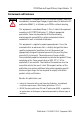
POINTBlock dc 8 Input/8 Relay Output Module 3 Environment and Enclosure ATTENTION This equipment is intended for use in a Pollution Degree 2 industrial environment, in overvoltage Category II applications (as defined in IEC publication 60664-1), at altitudes up to 2000 m without derating. This equipment is considered Group 1, Class A industrial equipment according to IEC/CISPR Publication 11.
POINTBlock dc 8 Input/8 Relay Output Module Prevent Electrostatic Discharge ATTENTION This equipment is sensitive to electrostatic discharge, which can cause internal damage and affect normal operation. Follow these guidelines when you handle this equipment. • Touch a grounded object to discharge potential static. • Wear an approved grounding wriststrap. • Do not touch connectors or pins on component boards. • Do not touch circuit components inside the equipment.
POINTBlock dc 8 Input/8 Relay Output Module 5 North American Hazardous Location Approval The following information applies when operating this equipment in hazardous locations Informations sur l’utilisation de cet équipement en environnements dangereux Products marked CL I, DIV 2, GP A, B, C, D are suitable for use in Class I Division 2 Groups A, B, C, D, Hazardous Locations and nonhazardous locations only.
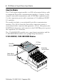
POINTBlock dc 8 Input/8 Relay Output Module About the Module This 1734D input/output module is a DIN-rail mounted device with an integrated DeviceNet communication interface, 8 inputs, 8 relay outputs, removable terminations, and a POINTBus expansion port. Use the expansion port to add a maximum of 12 additional POINT I/O modules. The module includes a non-isolated DeviceNet communication interface.
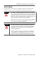
POINTBlock dc 8 Input/8 Relay Output Module 7 Install the Module For information about how to install the module, read this and the sections on how to set the node address and wire the module. ATTENTION This product is grounded through the DIN rail to chassis ground. Use zinc-plated, yellow-chromated steel DIN rail to assure proper grounding.
POINTBlock dc 8 Input/8 Relay Output Module Set Node Address Read this for information about how to set the node address. To set the node address, set the combination of ones and tens switches to correspond to the required address. For example, for 61, set the tens switch to six and the ones switch to one.
POINTBlock dc 8 Input/8 Relay Output Module 9 Wire the Module Refer to the figures that show how to wire the module. WARNING WARNING ATTENTION WARNING When you connect or disconnect the Removable Terminal Block (RTB) with field-side power applied, an electrical arc can occur. This could cause an explosion in hazardous location installations. Be sure that power is removed or the area is nonhazardous before proceeding.
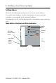
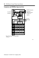
POINTBlock dc 8 Input/8 Relay Output Module Connectors and POINTBus Expansion Ports En 24 CH CL 5V CH DeviceNet Connector GND SH CL 24V to 5V RT POINTBus Expansion Port (allows expansion of up to 12 POINT I/O modules) Microprocessor Field Bus Connector I/O Circuits Power Connections 12/24V dc I/O Connections 41971 Publication 1734-IN021C-EN-P - September 2006
POINTBlock dc 8 Input/8 Relay Output Module 11 Wire the Module Field Power 0 NC NC NC 5 6 V 12/24V dc Power 1 2 3 C 7 C C 6 V 7 V RTB 0 6 7 V RTB 1 5 C C 6 7 V 0A 2 3 V RTB 2 0 1 5 4 5 0 1 4 2 3 4 Outputs 0 1 0 2 3 4 C V dc 0 1 NC 2 Inputs 1A 2 3 OB 1 4A 1B 5A 3 4B 4 5B 5 4 5 2A 3A 6A 7A 6 7 6 7 2B 3B 6B RTB 3 7B RTB 4 This supply is to be connected to the internal power bus.
POINTBlock dc 8 Input/8 Relay Output Module Channel, Input Terminal, Common, and Voltage for Terminal Blocks Channel Input Terminal Common Voltage 0…3 No Connection No Connection 4, 5 Common Removable Terminal Block 0 6, 7 Vin Removable Terminal Block 1 Channel Input Terminal Common Voltage 0 0 4 6 1 1 5 7 2 2 4 6 3 3 5 7 Removable Terminal Block 2 Channel Input Terminal Common Voltage 4 0 4 6 5 1 5 7 6 2 4 6 7 3 5 7 Connect common on 3-wire proximity
POINTBlock dc 8 Input/8 Relay Output Module 13 Relay Output Wiring (Load Powered by External Power) Field Power 0 NC 3 NC NC 4 5 C C 6 7 V RTB 0 1 3 C 6 C 7 V V RTB 1 7 6 RTB 2 3 OB 1 4A 2 1B 5A 3 4B 5B 5 4 5 C 2A 3A 6A 7A 6 7 6 7 V 2B 3B 6B 7B 7 V 1A 4 5 C 0A 2 3 0 1 5 6 4 5 0 1 4 2 3 2 4 Outputs 0 1 0 2 2 V 12/24V dc Power 0 1 NC V dc Inputs RTB 3 RTB 4 This supply will be connected to the internal power bus.
POINTBlock dc 8 Input/8 Relay Output Module Terminal, Output, Common, and Supply for Terminal Blocks Terminal Common Voltage 0…3 No connection No Connection 4, 5 Common Removable Terminal Block 0 6, 7 Vin Removable Terminal Block 4 Channel Output 0A 0 0B 2 1A 1 1B 3 2A 4 2B 6 3A 5 3B 7 Common Supply Common Supply Removable Terminal Block 4 Channel Output 4A 0 4B 2 5A 1 5B 3 6A 4 6B 6 7A 5 7B 7 Supply voltage can range from +5V dc…240V ac, depending on r
POINTBlock dc 8 Input/8 Relay Output Module 15 DeviceNet Connector Wiring DeviceNet Connection Red +V White CAN - High Bare Shield Blue Black CAN - Low -V 42132 When connecting more than one wire in a termination point, make sure that both wires are the same gauge and type.
POINTBlock dc 8 Input/8 Relay Output Module POINTBlock dc 8 Input/8 Relay Output Module - 1734D-IB8XOW8, 1734D-IB8XOW8S Attribute Value Field Power Bus Supply Voltage, Nom Voltage Range Supply Current, Max 24V dc 10…28.8V dc 10 A Communication Rate 125 Kbps (500 m max) 250 Kbps (250 m max) 500 Kbps (100 m max) Dimensions (HxWxD), Approx. 76.2 x 60.0 x 33.4 mm (3.00 x 2.36 x 5.25 in.) Conductors Wire Size 0.25…2.5 mm2 (22…14 AWG), solid or stranded copper rated @ 75 °C (167 °F) or higher 1.
POINTBlock dc 8 Input/8 Relay Output Module 17 Environmental Specifications Attribute Value Operational Temperature IEC 60068-2-1 (Test Ad, Operating Cold), IEC 60068-2-2 (Test Bd, Operating Dry Heat), IEC 60068-2-14 (Test Nb, Operating Thermal Shock): -20…55 °C (-4…131 °F) Storage Temperature IEC 60068-2-1 (Test Ab, Unpackaged Non-operating Cold) IEC 60068-2-2 (Test Bb, Unpackaged Non-operating Dry Heat) IEC 60068-2-14 (Test Na, Unpackaged Non-operating Thermal Shock) -40…85 °C (-40…185 °F) Relative
POINTBlock dc 8 Input/8 Relay Output Module Input Specifications - IEC 3 24V dc Input Compliant(1) Attribute Value On-state Voltage Range, Min 10V dc On-state Voltage Range, Nom 24V dc On-state Voltage Range, Max 28.8V dc On-state Current, Min 2.5 mA On-state Current, Nom 6.3 mA @ 24V dc On-state Current, Max 7.6 mA Off-state Voltage, Max 5V dc Off-state Current, Max 1.5 mA Input Impedance, Max 5.3 KΩ Input Delay Time OFF to ON ON to OFF 0.5 ms hardware + (0…65 ms selectable) 0.
POINTBlock dc 8 Input/8 Relay Output Module 19 Output Specifications Attribute Value Relay Type Form A, normally open, Single Pole, Single Throw Output Voltage Range, Resistive 5…28.8V dc @ 2.0 A 48V dc @ 0.5 A 125V dc @ 0.25 A 125V ac @ 2.0 A 240V ac @ 2.0 A Relay Output Current Rating, Inductive 2.0 A steady state @ 5…28.8V dc, L/R - 7 ms 0.5 A steady state @ 48V dc, L/R = 7 ms 0.25 A steady state @ 125V dc, L/R = 7 ms 2.0 A steady state, 15 A make @ 125V ac, PF = cos θ = 0.4 2.
Output Specifications Attribute Value Expected Contact Life 300 Kcycles resistive; 100 Kcycles inductive Off-state Leakage, Max 1.5 mA Output Delay Time 10 ms max ON/OFF Certifications Attribute Value Certifications C-UL-US UL Listed Industrial Control Equipment, certified for US and Canada. See UL File E65584. UL Listed for Class I, Division 2 Group A,B,C,D Hazardous Locations, certified for U.S. and Canada. See UL File E194810.