Very High-Speed Counter Modules 1734-VHSC5 and 1734-VHSC24 User Manual
Important User Information Solid state equipment has operational characteristics differing from those of electromechanical equipment. Safety Guidelines for the Application, Installation and Maintenance of Solid State Controls (Publication SGI-1.1 available from your local Rockwell Automation sales office or online at http://literature.rockwellautomation.com) describes some important differences between solid state equipment and hard-wired electromechanical devices.
Summary of Changes Summary of Changes This publication contains new and revised information not in the last release. New and Revised Information See the table for a summary of the major changes in this manual.
Summary of Changes 2 Notes: Publication 1734-UM003B-EN-P - August 2005
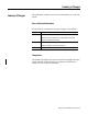
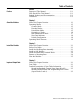
Table of Contents Preface Preface Purpose of This Manual. . . . . . . . . . . Who Should Use This Manual . . . . . . Related Products and Documentation. Definitions . . . . . . . . . . . . . . . . . . . . . . . . . . . . . . . . . . . . . . . . . . . . . . . . . . . . . . . . . . . . . . . . . . . . . . . . . . . . . . . . . . . . P-1 P-1 P-1 P-3 . . . . . . . . . . . . . . . . . . . . . . . . . . . . . . . . . . . . . . . . . . . . . . . . . . . . . . . . . . . . . . . . . . . . .
Configuration Data . . . . . . . . . . . . . . . . . . . . . . . . . . . . Counter Configuration (Configuration Word 1) . . . . . Filter Selection (Configuration Word 2 . . . . . . . . . . . Decimal Position (Configuration Word 3) . . . . . . . . . Word 4 is reserved. . . . . . . . . . . . . . . . . . . . . . . . . . Time Base and Gate Interval (Configuration Words 5 and 6) . . . . . . . . . . . . . . . . . . . . . . . . . . . . . . . . . Scalar (Configuration Word 7) . . . . . . . . . . . . . . . . .
Preface Purpose of This Manual Who Should Use This Manual Read this manual for information about how to install, configure, and troubleshoot your module.
Preface 2 Related Products and Documentation For specification, safety approval, and other information refer to the following. • Publication Number 1734-IN003 5V and 24V Very High-speed Counter Modules Installation Instructions For related 1734 products and documentation see the table. Publication 1734-UM003B-EN-P - August 2005 Description Cat. No.
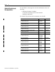
Preface Definitions 3 The following define the intended operation of the module. Term Definition Lead Breakage Typically requires a shunt resistor (across the load) to detect 3 levels of current/input states • Open (Wire Off, Device = ?) • Off (Wire OK, Device Off) • On (Wire OK, Device On) This method does not check the input against a time base, only that the device wiring (current loop) is intact. Missing Pulse Typically uses an input pulse to reset a watchdog timer (fixed or programmable HW).
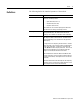
Preface 4 Operational Mode Zero Frequency Detection Input Monitored Counter No None Encoder No None Period/Rate Yes Z Only Y A Only Rate Measurement Publication 1734-UM003B-EN-P - August 2005
Chapter 1 About the Modules What This Chapter Contains Read this chapter to learn about types, features, and capabilities of the encoder/counter modules. Module Description and Features The modules install into the POINT I/O terminal base (1734-TB or 1734-TBS) and interface with the Point I/O DeviceNet Pass-through (1734-PDN) or the Point I/O DeviceNet Adapter (1734-ADN).
1-2 About the Modules The outputs are rated to source 0.5A at 10 to 28.8V dc. The output may be tied to an input. This lets you cascade counters of multiple 1734-VHSC modules. The counter has 4 user-selectable On-Off values (windows) associated with it. Tie either output to any or all of the window signals. Operating Modes The modules operate in the modes shown in the table. Mode Description Counter Mode Read read incoming single-phase pulses, return a binary count.
About the Modules 1-3 Channel A input is used as the counting pulse while channel B is used to determine the direction. [B = High, Count = Down; B = Low or floating (not connected), Count = Up] The Channel B input may be tied high or low for unidirectional counting, or toggled for bidirectional counting.
1-4 About the Modules Absolute encoders typically have higher speed requirements (200 KHz typical) for motion control applications. An absolute encoder has a unique code associated with each position, so the exact position is always known, even if the system power is turned off.
About the Modules 1-5 X4 Multiplying Encoder Mode Quadrature input signals are used to count on leading and trailing edges of A and B for a bidirectional count, and channel B is used to determine the direction. [ B = leads A, Count = Down; B = follows A, Count = Up ] Period/Rate Mode The Period/Rate mode returns an incoming frequency and a total accumulated count to the POINTBus, by gating an internal 5 MHz internal clock with an external signal.
1-6 About the Modules As the frequency of the incoming pulse train at the Z (Gate/Reset) terminal increases, the number of sampled pulses from the 5MHz clock decreases. Since accuracy is related to the number of pulses received over the sample period, the accuracy decreases with increasing frequencies at the Gate/Reset terminal. Refer to the following Scaling table.
About the Modules 1-7 Continuous/Rate Mode The Continuous/Rate Mode returns an incoming frequency and a total accumulated count to POINTBus, by gating an internal 5 MHz internal clock with an external signal. Similar to the Period/Rate mode except outputs in this mode are updated continuously. This mode determines the frequency and total number of input pulses by counting the number of internal 5 MHz clock pulses over a user-specified number of input signal pulses.
1-8 About the Modules Rate Measurement Mode The Rate Measurement mode determines the frequency and total number of input pulses over a user-specified sample period. At the end of the interval, the module returns a value representing the sampled number of pulses and a value indicating the incoming frequency. When you update the count and frequency, you check any associated outputs against their associated presets.
About the Modules 1-9 New Data Indicator A two-bit counter, C1 and C0, is updated every time an event occurs, indicating that new data is available in the Stored/Accumulated Count words.
1-10 About the Modules Operating Mode Features See the table for a summary of features active in each mode.
About the Modules 1-11 Store Count Mode 2: Store/Wait/Resume In mode 2, the rising edge of a pulse input on the Z Gate/Reset terminal reads and stores the current counter value in the Stored/Accumulated Count word and inhibit counting while the Z Gate/Reset terminal is high. Counting resumes on the falling edge of the pulse at the Z Gate/Reset terminal. The stored count information remains until it is overwritten with new data.
1-12 About the Modules Store-Reset/Start Start Counting Store Count, and Reset to zero Continue Counting Output Control To connect an output to a compare window, you could program the module accordingly: • Tie Output 0 to Window 0 • Program Window 0 ON Value to 2000 • Program Window 0 OFF Value to 5000 ON-OFF Operation of Output 0 Output remains energized for 3000 additional counts Output turns ON at count value of 2000 Output turns OFF at count value of 5000 If the OFF value is greater than the ON
Chapter 2 Install the Module What This Chapter Contains Read this chapter for information about how to install the modules. The 1734-VHSC module is a two-module set. Module 1 houses the 1734-VHSC functionality while module 2 provides screw terminals necessary to access chassis ground (Chas Gnd) and common (C). Module 2 also connects terminal 4 to 5 and terminal 6 to 7 for ease of wiring power to the input device. Module 2 is not necessary for VHSC functionality but eases customer wiring.
2-2 Install the Module ATTENTION Environment and Enclosure This equipment is intended for use in a Pollution Degree 2 industrial environment, in overvoltage Category II applications (as defined in IEC publication 60664-1), at altitudes up to 2000 meters without derating. This equipment is considered Group 1, Class A industrial equipment according to IEC/CISPR Publication 11.
Install the Module The wiring base assembly (1734-TB or 1734-TBS) consists of a mounting base (cat. no. 1734-MB) and a removable terminal block (cat. no. 1734-RTB or 1734-RTBS). You can install the assembly, or just the mounting base. To install the mounting base and wiring base assembly on the DIN rail, proceed as follows. ATTENTION POINT I/O is grounded through the DIN rail to chassis ground. Use zinc-plated, yellow-chromated steel DIN rail to assure proper grounding.
2-4 Install the Module 3. Press firmly to seat the mounting base on the DIN rail. The mounting base snaps into place. M Stod ule atus Net Statwor us k NO DE : 0 24 So VDC Ouurce tput 1 2 3 17 OB34 4E 44013 ATTENTION Install the Module Do not discard the end cap shipped with an adapter or communication interface. Use this end cap to cover the exposed interconnections on the last mounting base on the DIN rail. Failure to do so could result in equipment damage or injury from electric shock.
Install the Module 2-5 1. Using a bladed screwdriver, rotate the keyswitch on the mounting base clockwise until the number required for the type of module you are installing aligns with the notch in the base. 1734-VHSC24 - Position 2 1734-VHSC5 - Position 2 Turn the keyswitch to align the number with the notch. Notch (position 3 shown) 44009 2. Make certain the DIN rail locking screw is in the horizontal position, noting that you cannot insert the module if you unlock the locking mechanism.
2-6 Install the Module Install the Removable Terminal Block A removable terminal block comes with your mounting base assembly. Pull up on the RTB handle to remove and replace as necessary without removing any of the wiring. To reinsert the removable terminal block, use this procedure. 1. Insert the RTB end opposite the handle into the base unit. This end has a curved section that engages with the mounting base. Hook the RTB end into the mounting base end, and rotate until it locks into place. 44011 2.
Install the Module 2-7 2. Pull on the RTB handle to remove the removable terminal block. WARNING When you connect or disconnect the removable terminal block (RTB) with field-side power applied, an electrical arc can occur. This could cause an explosion in hazardous location installations. Be sure that power is removed or the area is nonhazardous before proceeding. 3. Press in on the module lock on the top of the module, and pull up on the I/O module to remove from the base. 4.
2-8 Install the Module Module Status Network Status Status of Input A Status of Input B Status of Input Z 0 0 1 1 Status of Output 0 Status of Output 1 Input A Input Aret Chassis Ground Chassis Ground Input B Input Bret RET 0 RET 1 Input Z Input Zret -Vaux -Vaux Out 0 Out 1 +Vaux +Vaux 42016 Module 1 1 0 A 2 3 6 Publication 1734-UM003B-EN-P - August 2005 Chas Gnd 2 Bret 5 7 Out 0 RET 0 4 Zret Z 1 0 Aret B 4 Module 2 Out 1 Chas Gnd 3 RET 1 5 -Vaux -Vaux 6 7
Chapter 3 Very High-Speed Counter Module Input and Output Data What This Chapter Contains Data Table In this chapter, you learn about the input and output data table of your 1734-VHSC24 and 1734-VHSC5 Modules. For More Information About See Page Data Table 3-1 Detailed Description of Data Table Information 3-2 Output Data 3-5 Configuration Data 3-6 Communicating Real Time Information 3-11 The following table shows the complete format of the input and output data.
3-2 Very High-Speed Counter Module Input and Output Data 15 07 06 05 04 03 02 01 0 Output Ties 0 0 0 0 0 T3 T2 T1 T0 Output Ties 1 0 0 0 0 T3 T2 T1 T0 Scalar 14 13 12 11 10 09 8-bit value used to divide the Z input by 2 08 n Rollover Value 32-bit value at which the counter is commanded to rollover Preset Value 32-bit value the counter is to be set to when CP is asserted On Value 1 32-bit value that sets the compare window Off Value 1 32-bit value that sets the c
Very High-Speed Counter Module Input and Output Data 3-3 Finally, in rate measurement [7] configuration, it is the total number of pulses seen at the A input accumulated over each period as specified by the product of the time base x gate interval. The range of values occupy the entire 32-bit size from 0 ≤value ≤0xFFFFFFFF (4,294,967,295). Changing the configuration does not clear these words.
3-4 Very High-Speed Counter Module Input and Output Data EEPROM Fault status bit (EF) - If a fault is detected with the EEPROM during power up tests, this bit is asserted to 1. It indicates that the content of the EEPROM has been corrupted, most likely caused by loss of power during an executing write. Not Ready status bit (NR) - Whenever power is applied to the module, the hardware must be initialized. During this time, the NR bit is asserted and the green module status indicator flashes.
Very High-Speed Counter Module Input and Output Data Output Data 3-5 Counter Control (Word 1) VR Value Reset of stored/accumulated count. The transition of this bit from 0 to 1 clears the stored/accumulated count word. CP Counter Preset. The transition of this bit from 0 to 1 sets the counter to the value specified by the Preset words. Outputs are adjusted according to the window compare values. CR Counter Reset. The transition of this bit from 0 to 1 clears the counter.
3-6 Very High-Speed Counter Module Input and Output Data Pulse Width Modulation (PWM) Value (Output Word 3) When the module is programmed for a PWM [3] configuration, the time base is enabled, the counter rollover, which is defined as the 1st ON and 1st OFF value for the respective channel is used. Ties can be used to direct the PWM signal to any or both outputs. The range of PWM values is 0 ≤value ≤9500 decimal (0.00% ≤value ≤95.00%).
Very High-Speed Counter Module Input and Output Data 3-7 Filter Selection (Configuration Word 2) This byte sets the A/B/Z input filters. Filter Selection 07 06 05 04 0 ZF BF AF 03 02 01 00 FS 0 0 0 0 No Filter 0 0 0 1 50 kHz (10 µs + 0 µs/-1.6 µs) 0 0 1 0 5 kHz (100 µs + 0 µs/-13.2 µs) 0 1 0 0 500 Hz (1.0 ms + 0 µs/-125 µs) 1 0 0 0 50 Hz (10 ms + 0 ms/-1.
3-8 Very High-Speed Counter Module Input and Output Data In the counter modes (counter [0], x1 encoder [1], x2 encoder [2], pwm [3], x4 encoder [4]), it attenuates the counter display, for example, 20 divides count+1 by 20. The value may be in the range 0 < value ≤255. The result of requesting a number other than 1 performs the function: (COUNT + 1) / ATTENUATION. This is useful for scaling a large counter value to a smaller 16-bit value or a percentage.
Very High-Speed Counter Module Input and Output Data 3-9 Scalar (Configuration Word 7) This byte scales the Z signal in the period/rate [5] and continuous/rate [6] configurations. If the filter is applied, then the filtered Z is scaled. Only one bit of the scalar should be set. Selecting a scalar causes accumulated counts to be adjusted accordingly. Selecting a scalar of 128 increases the accumulated count by 128 after 128 Z pulses are received.
3-10 Very High-Speed Counter Module Input and Output Data Rollover (Configuration Word 10) This long word sets the number of counts the counter accumulates before rolling over. For example, a value of 1000 produces a count sequence of: 998, 999, 0, 1, 2… while incrementing or 2, 1, 0, 999, 998… while decrementing. Rollover is a 32-bit number with a useable range of 1 ≤value ≤0x01000000 (16,777,216).
Very High-Speed Counter Module Input and Output Data 3-11 Safe State Values (Configuration Words 20 through 22) When either the host transitions to PROGRAM mode or a communication fault (broken network cable) occurs, the module copies these safe state words (counter control, output control, and PWM value) into its real-time working buffer.
3-12 Very High-Speed Counter Module Input and Output Data #108 (0x6c) Publication 1734-UM003B-EN-P - August 2000 Set/Get Counter Configuration 1 Filter Selection 1 Decimal Position 1 Active Output Assembly 1 Time Base or PWM Period 2 Gate Interval 1 Scalar 1 Output 0 Ties 1 Output 1 Ties 1 Rollover Value 4 Preset Value 4 ON Value # 1 4 OFF Value #1 4 ON Value # 2 4 OFF Value #2 4 ON Value # 3 4 OFF Value #3 4 ON Value # 4 4 OFF Value #4 4 PWM Safe State Value 2 C
Chapter 4 Configure Your Module What This Chapter Contains This chapter describes how to configure your Very High-Speed Counter modules with RSNetWorx. For More Information About Configuration Overview See Page Configuration Overview 4-1 Add the Adapter to Your Network 4-1 Add I/O Modules to Your Network 4-2 Set the Counter’s Parameters 4-5 Check I/O Status and View the EDS File 4-9 Use RSNetWorx for DeviceNet software to configure your module.
4-2 Configure Your Module The scanner appears on the network. 1. Click here to expand the list of communication adapters. 2. Double-click here to choose the scanner. You can also click and drag the scanner name onto the network. Make sure you choose the 1734-ADN POINT I/O Scanner. Add I/O Modules to Your Network After you add the communication device, you must add the POINT I/O modules connected to the scanner on the POINTBus. Use these procedures. 1.
Configure Your Module 4-3 The out-of-the-box node setting for 1734 modules is 63. You can change the setting by using the node commissioning tool. The node commissioning tool is available either online or offline. IMPORTANT If you commission a node online, you must power down your system before the change takes place. 1. Click here to expand the list of Specialty modules. 2. Double-click the catalog number to choose the module. You can also click and drag the module name onto the network.
4-4 Configure Your Module 3. From the DeviceNet - RSNetWorx for DeviceNet dialog, complete the actions shown in the figure. 1 2 3 4 5 6 Publication 1734-UM003B-EN-P - August 2005 1. Go to the pulldown Tools. Select Node Commissioning. 2. Click Browse. 3. Select the module to change. 4. The node commissioning dialog returns. It displays the node number and data rate. 5. Change the node number and Apply. The dialog then identifies the new setting. 6. Click Close to continue.
Configure Your Module Set the Counter’s Parameters 4-5 After adding the module to the network, you must configure the modules for use. Use this procedure. IMPORTANT This procedure shows configuration in the online mode. Changes set in this mode take effect when you download to the individual module. 1. From the DeviceNet - RSNetWorx for DeviceNet dialog, complete the actions shown in the figure. 1. Right-click the module. You can also left-click the module or name and the property dialog appears. 2.
4-6 Configure Your Module 2. From the counter module dialog, complete the actions shown in the figure for the General dialog. The module’s name appears here. Type a description here. The module’s address appears here. (This field is read only.) This dialog also shows the module’s device identity. These fields are read-only. At any point, you can click here to finish changing configuration parameters. If configuration changes are made in offline mode, they do not take effect until the system goes online.
Configure Your Module 4-7 3. From the General dialog, click Device Parameters and complete the actions shown in the figure. This dialog appears after clicking the Device Parameters tab. If you want the existing parameters uploaded from the module, select Upload. The following dialog then shows the existing parameters set on the module. Use this pulldown menu to edit or view the parameters.
4-8 Configure Your Module 4. To configure your module, from the Device Parameters dialog, select Configuration and complete the actions in the figure. To configure your module, select Configuration and modify the parameters as desired for your application. When complete, download to your module by clicking the Download to Device button. You can download each change as you make it using “Single,” or download all your changes using “All.” Click here when finished.
Configure Your Module Check I/O Status and View the EDS File 4-9 Use this procedure to complete the entries on the dialogs you display by clicking the appropriate tab for I/O Defaults and EDS File. 1. From the Counter Module screen, click I/O Defaults from the top of the dialog, completing the entries shown in the figure. Click the I/O Defaults tab to display the default characteristics for this module. This dialog shows the input/output defaults for the four modes.
4-10 Configure Your Module 2. From the Counter Module dialog, click EDS File from the top of the dialog, completing the entries shown in the figure. Click the EDS File tab to display the statistics of the EDS file used to configure this module. Click View File to view the actual EDS file (shown at the left). You can view the actual EDS file or edit the file.
Chapter 5 Access Instantiated Instances What This Chapter Contains In this chapter, you learn how to access imbedded Instantiated Instances (assemblies) in the software. The Very High-Speed Counter Module uses several words to communicate real time input and output data as well as non-real time module information (such as description and revision) and configuration. These words have been preprogrammed into Instantiated Instances.
5-2 Access Instantiated Instances 2. From the Service Class Instance Attribute Editor Warning dialog, click Yes. You see the Service Class Instance Attribute Editor dialog. 3. From the Service Class Instance Attribute Editor dialog, complete these actions, referring to the figure. a. Select the service code. b. For Recevie Data, select Size and Radix. c. Enter the class, instance, and attribute. d. Click Execute to initiate the action. e. Click Close to finish. a. Select the service code from the list.
Access Instantiated Instances 5-3 See the figure for an example, where you select Instance 101 (polled connection). 1. Type in the instance number here. This is an example of assembly number 102 (0x66). The class is always 4 and the attribute is always 3. 2. Click Execute. 3. Data received and status information is recorded here. 4. Click Close to finish. Assemblies Available assemblies are: • Assembly 101 is produced for a polled connection.
5-4 Access Instantiated Instances Instances Services Field Bytes #101 (0x65) Get Present Channel Data 4 Status 2 Stored Channel Data 4 Status 2 Present Channel Data 4 Stored Channel Data 4 Status 2 #102 (0x66) #103 (0x67) Get #104 (0x68) Get Programming Error Code 2 #105 (0x69) Set/Get Counter Control 1 Output Control 1 #106 (0x6a) Set/Get PWM Value 2 #107 (0x6b) Set/Get PWM Value 2 Counter Control 1 Output Control 1 Counter Configuration 1 Filter Selection
Chapter 6 Troubleshoot with the Indicators Use the Indicators for Troubleshooting Each 1734-VHSC module has 7 indicators on the frontplate. Use these indicators for troubleshooting, referring to the figures and tables. Module Status Network Status Status of Input A 0 1 Status of Input B Status of Input Z Status of Output 0 Status of Output 1 Indication Probable Cause Module Status 1 Off No power applied to device. Green Device is operating normally.
6-2 Troubleshoot with the Indicators Indication Probable Cause Network Status Off Device is not online. - Device has not completed dup_MAC_id test. - Device not powered - check module status indicator. Flashing Green Device is online but has no connections in the established state. Green Device is online and has connections in the established state. Flashing Red One or more I/O connections are in timed-out state Red Critical link failure is present - failed communication device.
Appendix A Configure Modules in RSLogix 5000 Software What This Appendix Contains Read this appendix for information about how to configure your modules in RSLogix 5000 software, including how to complete entries on these dialogs. • Fault/Program Action • Counter Configuration • Output Configuration Understand Data, Connection, and Communication Formats Before you configure your modules, note the following about Data formats and Connection types. • Data format type is Integer.
A-2 Configure Modules in RSLogix 5000 Software When you change Connection and Data Format note the following. • You do not delete the existing module. • You do not create a new module. • You bring forward all possible configuration data for the new setting. • Configuration data that you cannot bring forward sets to the default value. Once you apply new settings, this becomes the base configuration for the next change in Connection and Data Format settings.
Configure Modules in RSLogix 5000 Software Configure Your Module A-3 To configure your module in RSLogix 5000, use this procedure. 1. Configure your adapter, referring to the user manual for your adapter for information on how to configure the adapter and add modules to the I/O configuration to include selecting a controller and communication module. 2. Add a 1734-VHSC3 or 1734-VHSC24 specialty module, according to the instructions in your adapter user manual. 3.
A-4 Configure Modules in RSLogix 5000 Software Work with the Fault/Program Action Dialog Use these procedures to complete the entries from this dialog, which is not available with a Listen Only connection. 1. Check the checkboxes, as shown in the table. Check this Checkbox To Counter Reset Reset the counter Counter Preset Set the value of the counter, as specified by the preset words Value Reset Reset the value of the accumulated (stored) count 2.
Configure Modules in RSLogix 5000 Software A-5 3. For the appropriate Output number, check the checkboxes for the values in the table. Value Description Force Output If checked, you turn outputs on if you check Output Enable. If unchecked, you control the outputs by a compare match or as directed by the PWM settings. Output Enable If checked, you permit outputs to turn on from one of the these.
A-6 Configure Modules in RSLogix 5000 Software Work with the Counter Configuration Dialog In Hard Run mode, you disable all controls on the Counter Configuration dialog, in addition to the enable and disable state for each control. Use the following procedures to complete entries from this dialog. After you select Type, refer to the table to see what other entries are available in the dialog.
Configure Modules in RSLogix 5000 Software A-7 1. For Type, select one of these to set the Counter Configuration mode. • • • • • • • Counter (default) Encoder X1, Encoder X2, or Encoder X4 Pulse Width Modulation (PWM) Period/Rate Continuous Rate Rate Measurement Pulse Generator 2. Refer to the table to see what entries to complete based on your selection for Type. 3. For Store Count Mode, select an option to determine which of the following modules you use for operating the Z Gate/Reset Terminal.
A-8 Configure Modules in RSLogix 5000 Software 9. For Time Base, select a value between 10 and 3000 milliseconds, in multiples of 10, referring to the table. Selections for Period/Rate and Rate Measurement For This Value Default Is: Select Frequency Precision X1 X 0.0001 X 0.001 X 0.01 X 0.1 X1 X 10 X 100 Gate Multiplier 1 1 to 200 Time Base 1000 10 to 3000 in multiples of 10 10.
Configure Modules in RSLogix 5000 Software A-9 14. For Scalar, choose one of these. •1 •2 •4 •8 • 16 • 32 • 64 • 128 When the value for Scalar is one of the following, note that frequency precision < 1. • • • • 16 32 64 128 15. Complete one of these. • Click another tab at the top of the dialog. or • Click OK, which closes the dialog. or • Click Cancel to return to default values.
A-10 Configure Modules in RSLogix 5000 Software Work with the Output Configuration Dialog Use this dialog to make On Value and Off Value entries for each output you select. If you make no entries for Outputs on this dialog, leave On Value and Off Value entries as 0; otherwise, use these procedures. 1. Check a checkbox for Outputs. 2. Select entries for On Value and Off Value, referring to the table. 3. Complete one of these. • Click another tab at the top of the dialog.
Index A active features per mode 1-10 assembly selection 3-8, 3-11 B base assembly, mounting 2-1 C checking I/O defaults 4-6 class instance attribute editor 5-2 class instance editor 5-1 commissioning a node 4-2 compare window on/off values 3-10 configuration data 3-6 configuration software 4-1 connecting an output to a compare window 1-12 connecting outputs to compare windows 3-9 continuous/rate measurement mode 1-2 continuous/rate mode - operation 1-7 counter control 3-5 counter mode 1-2 counter mode o
2 Index P parameter setting 4-4 period rate mode - operation 1-5 period/rate mode 1-2 positioning the keyswitch 2-3 present channel data 3-2 preset configuration 3-10 pulse width modulation mode 1-2 pulse width modulation mode operation 1-8 pulse width modulation output word 3-6 PWM mode 1-2 PWM timebase selection 3-8 scalar selection 3-9 selecting a filter 3-7 selecting counter type 3-6 selecting the scalar setting 3-9 setting module parameters 4-4 setting rollover counts 3-10 setting safe state values
How Are We Doing? Your comments on our technical publications will help us serve you better in the future. Thank you for taking the time to provide us feedback. You can complete this form and mail (or fax) it back to us or email us at RADocumentComments@ra.rockwell.com Pub. Title/Type Very High-Speed Module Cat. No. 1734-VHSC5 VHSC24 Pub. No. 1734-UM006B-EN-P Pub. Date August 2005 Part No. 957974-42 Please complete the sections below.
PLEASE FASTEN HERE (DO NOT STAPLE) PLEASE FOLD HERE NO POSTAGE NECESSARY IF MAILED IN THE UNITED STATES BUSINESS REPLY MAIL FIRST-CLASS MAIL PERMIT NO.
Back Cover Publication 1734-UM003B-EN-P - August 2005 6 Supersedes Publication 1734-UM003A-EN-P- August 2000 PN 957974-42 © 2005 Rockwell International Corporation. Printed in the U.S.A.