Installation Instructions POINT I/O 5V DC and 24V DC Very High Speed Counter Module Catalog Numbers 1734-VHSC5, 1734-VHSC24, Series C Table of Contents Topic Page Important User Information 2 Environment and Enclosure 3 Preventing Electrostatic Discharge 3 North American Hazardous Location Approval 4 European Hazardous Location Approval 5 Additional Resources 6 About the Module 6 Install the Mounting Base 8 Install the Module 8 Install the Removable Terminal Block 10 Remove a Mounting
POINT I/O 5V DC and 24V DC Very High Speed Counter Module Important User Information Solid-state equipment has operational characteristics differing from those of electromechanical equipment. Safety Guidelines for the Application, Installation and Maintenance of Solid State Controls (Publication SGI-1.1 available from your local Rockwell Automation sales office or online at http://www.rockwellautomation.
POINT I/O 5V DC and 24V DC Very High Speed Counter Module 3 Environment and Enclosure ATTENTION: This equipment is intended for use in a Pollution Degree 2 industrial environment, in overvoltage Category II applications (as defined in IEC 60664-1), at altitudes up to 2000 m (6562 ft) without derating. This equipment is not intended for use in residential environments and may not provide adequate protection to radio communication services in such environments.
POINT I/O 5V DC and 24V DC Very High Speed Counter Module North American Hazardous Location Approval The following information applies when operating this equipment in hazardous locations: Informations sur l'utilisation de cet équipement en environnements dangereux: Products marked "CL I, DIV 2, GP A, B, C, D" are suitable for use in Class I Division 2 Groups A, B, C, D, Hazardous Locations and nonhazardous locations only.
POINT I/O 5V DC and 24V DC Very High Speed Counter Module 5 European Hazardous Location Approval European Zone 2 Certification. The following applies when the product bears the Ex Marking. ATTENTION: This equipment is intended for use in potentially explosive atmospheres as defined by European Union Directive 94/9/EC.
POINT I/O 5V DC and 24V DC Very High Speed Counter Module Additional Resources Refer to the POINT™ I/O Very High-Speed Counter Module User Manual, publication 1734-UM003, for more information on how to use the module. You can view or download publications at http://www.rockwellautomation.com/literature/. To order paper copies of technical documentation, contact your local Rockwell Automation distributor or sales representative.
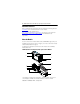
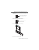
POINT I/O 5V DC and 24V DC Very High Speed Counter Module 7 Module Description Description Description 1 Module locking mechanism 6 Slide-in writable label 2 Module locking mechanism 7 Insertable I/O module 3 DIN rail locking screw (orange) 8 Removable terminal block handle 4 Mechanical keying (orange) 9 Removable terminal block (RTB) 5 Interlocking side pieces 10 Mounting base Before You Begin The modules referred to in this publication are as follows: • 1734-VHSC5, Series C POINT
POINT I/O 5V DC and 24V DC Very High Speed Counter Module Install the Mounting Base To install the mounting base on the DIN rail, proceed as follows: ATTENTION: This product is grounded through the DIN rail to chassis ground. Use zinc plated yellow-chromate steel DIN rail to assure proper grounding. The use of other DIN rail materials (for example, aluminum or plastic) that can corrode, oxidize, or are poor conductors, can result in improper or intermittent grounding.
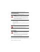
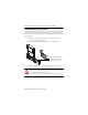
POINT I/O 5V DC and 24V DC Very High Speed Counter Module 9 1. Using a bladed screwdriver, rotate the keyswitch on the mounting base clockwise until the number required for the type of module being installed aligns with the notch in the base. Turn the keyswitch to align the number with the notch (position 3 is shown). 44009 2. Make certain the DIN rail locking screw is in the horizontal position. You cannot insert the module if the locking mechanism is unlocked.
POINT I/O 5V DC and 24V DC Very High Speed Counter Module Install the Removable Terminal Block A removable terminal block (RTB) is supplied with your wiring base assembly. To remove, pull up on the RTB handle. This allows the mounting base to be removed and replaced as necessary without removing any of the wiring. To reinsert the removable terminal block, proceed as follows: 1. Insert the end opposite the handle into the base unit. This end has a curved section that engages with the wiring base. 2.
POINT I/O 5V DC and 24V DC Very High Speed Counter Module 11 Remove a Mounting Base To remove a mounting base, you must remove any installed module, and the module installed in the base to the right. Remove the removable terminal block, if wired. 1. Unlatch the RTB handle on the I/O module. WARNING: When you connect or disconnect the Removable Terminal Block (RTB) with field side power applied, an electrical arc can occur. This could cause an explosion in hazardous location installations.
POINT I/O 5V DC and 24V DC Very High Speed Counter Module Wire the Module Module status Network status Status of input A Status of input B Status of input Z Status of output 0 Status of output 1 0 0 1 1 Input A Input Aret Chassis ground Input B Input Bret RET 0 RET 1 Input Z Input Zret -Vaux -Vaux Out 1 +Vaux +Vaux Out 0 Chassis ground WARNING: If you connect or disconnect wiring while the field-side power is on, an electrical arc can occur.
POINT I/O 5V DC and 24V DC Very High Speed Counter Module Module 2 Module 1 0 A 0 3 2 Aret 2 B 1 Bret 4 Out 0 5 -Vaux 7 Out 1 RET 1 4 Zret 6 Chas gnd Module 1 Terminations 1 3 RET 0 5 Z Chas gnd -Vaux 6 7 +Vaux +Vaux 13 Module 2 Terminations 0 A 0 Chassis ground 1 Aret 1 Chassis ground 2 B 2 Out 0 RET 3 Bret 3 Out 1 RET 4 Z 4 Vaux - 5 Zret 5 Vaux - 6 Out 0 6 Vaux + 7 Out 1 7 Vaux + Communicate with Your Module POINT I/O modules send (consume
POINT I/O 5V DC and 24V DC Very High Speed Counter Module Default Data Map Message size: 6 or 10 Bytes 15 14 13 12 11 10 09 08 07 06 05 04 03 02 01 00 Produces (scanner Rx) Channel 0 value of present counter state (LSW) Channel 0 value of present counter state (MSW) PE Where: EF NR 0 FS FS OS OS 0 ZS BS AS C1 C0 ZD 0 LSW = Least significant word MSW = Most significant word PE = Programming error EF = EEPROM fault status NR = Not ready status bit FS = Output fault status bit – bit 10 fo
POINT I/O 5V DC and 24V DC Very High Speed Counter Module 15 Module Configuration Parameter Set/Get Description 1 Set/Get Counter configuration Bytes 1 2 Set/Get Filter selection 1 3 Set/Get Decimal position 1 4 Set/Get Active output assembly 1 5 Set/Get Time base value 2 6 Set/Get Gate interval 1 7 Set/Get Channel scalar 1 8 Set/Get Output 0 ties 1 9 Set/Get Output 1 ties 1 10 Set/Get Channel rollover value 4 11 Set/Get Channel preset value 4 12 Set/Get ON
POINT I/O 5V DC and 24V DC Very High Speed Counter Module Counter Configuration 07 06 ZI 05 04 MD 03 02 01 00 Counter 0 0 0 0 0 Counter 0 0 0 1 Encoder X1 0 0 1 0 Encoder X2 0 0 1 1 PWM 0 1 0 0 Encoder X4 0 1 0 1 Period/Rate 0 1 1 0 Continuous/Rate 0 1 1 1 Rate measurement 1 0 0 0 CF Pulse generator 0 0 0 Store count disabled 0 0 1 Mode 1 – store/continue 0 1 0 Mode 2 – store/wait/resume 0 1 1 Mode 3 – store, reset/wait/start 1 0
POINT I/O 5V DC and 24V DC Very High Speed Counter Module 17 Filter Selection 07 06 05 04 03 0 ZF BF AF FS 02 01 00 0 0 0 0 0 No filter 0 0 0 1 50 kHz (10 μs + 0 μs/-1.6 μs) 0 0 1 0 5 kHz (100 μs + 0 μs/-13.2 μs) 0 1 0 0 500 Hz (1.0 ms + 0 ms/-125 μs) 1 0 0 0 50 Hz (10 ms + 0 ms/-1.25 ms) 0 A input not filtered 1 A input filtered 0 B input not filtered 1 B input filtered 0 Z input not filtered 1 Z input filtered Assumes a 50% duty cycle signal.
POINT I/O 5V DC and 24V DC Very High Speed Counter Module configuration. The table shows the words you can exchange. You can read (get) or write (set) data using an Explicit Message.
POINT I/O 5V DC and 24V DC Very High Speed Counter Module 19 Assemblies Instances (Dec/Hex) #123 (0x7b) Services Set/Get Field Bytes OFF value #2 4 ON value #3 4 OFF value #3 4 ON value #4 4 OFF value #4 4 PWM safe state value 2 Counter control SSV 1 Output control SSV 1 Counter configuration 1 Filter selection 1 Decimal position 1 Reserved (set to 0) 1 Time base or PWM period 2 Gate interval 1 Scalar 1 Output 0 ties 1 Output 1 ties 1 Alignment (reserved = 0) 2 Ro
POINT I/O 5V DC and 24V DC Very High Speed Counter Module Interpret Status Indicators Refer to the following diagram and table for information on how to interpret the status indicators. POINT I/O 5V DC and 24V DC Very High Speed Counter Module Module status Network status Status of input A Status of input B Status of input Z Status of output 0 Status of output 1 0 1 0 1 Indicator Status for Modules Module status Status Description Off No power applied to device.
POINT I/O 5V DC and 24V DC Very High Speed Counter Module 21 Indicator Status for Modules Status Network status Off Description Device is not online: – Device has not completed dup_MAC-id test. – Device is not powered – check module status indicator. Flashing green Device is online but has no connections in the established state. Green Device is online and has connections in the established state. Flashing red One or more I/O connections are in timed-out state.
POINT I/O 5V DC and 24V DC Very High Speed Counter Module Specifications Input Specifications Attribute Value Number of inputs 1 – 1 group of A/Aret, B/Bret and Z/Zret Input voltage 1734-VHSC5 – 5V DC 1734-VHSC24 – 24V DC Input current 1734-VHSC5 19.1 mA @ 5V DC 25.7 mA @ 6V DC 1734-VHSC24 6.1 mA @ 15V DC 10.2 mA @ 24V DC Input OFF-state current, max ≤ 0.250 mA Input OFF-state voltage 1734-VHSC5 – ≤ 1.25V DC 1734-VHSC24 –≤ 1.
POINT I/O 5V DC and 24V DC Very High Speed Counter Module 23 Output Specifications Attribute Value Number of outputs 1 isolated group of 2 capable of 0.5 A @ 24V DC Output control Outputs can be tied to any of 4 compare windows Output supply voltage range 10…28.8V DC OFF-state leakage current ≤ 0.5 mA ON-state voltage drop ≤ 0.3V DC @ 0.5 A ON-state current 0.
POINT I/O 5V DC and 24V DC Very High Speed Counter Module General Specifications Attribute Value Terminal base screw torque 0.6 Nm (7 lb-in.) Module location 1734-TB, 1734-TBS wiring base assembly POINTBus current, max 180 mA Power dissipation, max @ rated load 1734-VHSC5 – 1.5 W 1734-VHSC24 – 1.9 W Thermal dissipation, max @ rated load 1734-VHSC5 – 5.1 BTU/hr 1734-VHSC24 – 6.
POINT I/O 5V DC and 24V DC Very High Speed Counter Module 25 Environmental Specifications Attribute Value Temperature, operating IEC 60068-2-1 (Test Ad, Operating Cold), IEC 60068-2-2 (Test Bd, Operating Dry Heat), IEC 60068-2-14 (Test Nb, Operating Thermal Shock): -20…55 °C (-4…131 °F) Temperature, surrounding air, max.
POINT I/O 5V DC and 24V DC Very High Speed Counter Module Certifications Certification (when Value product is marked)(1) c-UL-us UL Listed Industrial Control Equipment, certified for US and Canada. See UL File E65584. UL Listed for Class I, Division 2 Group A,B,C,D Hazardous Locations, certified for U.S. and Canada. See UL File E194810. CE European Union 2004/108/EC EMC Directive, compliant with: EN 61326-1; Meas./Control/Lab.
POINT I/O 5V DC and 24V DC Very High Speed Counter Module 27 Input Derating Curve for 1734-VHSC24 28.8 Input Voltage (V) 24 20 10 10 20 30 40 45 50 Module Ambient Still Air Temperature (°C) IMPORTANT 55 Exceeding the maximum input voltage can cause permanent damage to the input.
Rockwell Automation Support Rockwell Automation provides technical information on the Web to assist you in using its products. At http://www.rockwellautomation.com/support/, you can find technical manuals, a knowledge base of FAQs, technical and application notes, sample code and links to software service packs, and a MySupport feature that you can customize to make the best use of these tools.