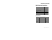
Installation Instructions POINT I/O One-piece Terminal Bases Catalog Numbers 1734-TOP, 1734-TOPS, 1734-TOP3, 1734-TOP3S Topic Page About This Publication 1 Important User Information 2 Environment and Enclosure 3 Prevent Electrostatic Discharge 4 Install a Base 5 Remove a Base 6 Specifications 7 About This Publication Read this publication for information about these terminal bases.
POINT I/O One-piece Terminal Bases Important User Information Solid state equipment has operational characteristics differing from those of electromechanical equipment. Safety Guidelines for the Application, Installation and Maintenance of Solid State Controls (publication SGI-1.1 available from your local Rockwell Automation sales office or online at http://literature.rockwellautomation.com) describes some important differences between solid state equipment and hard-wired electromechanical devices.
POINT I/O One-piece Terminal Bases 3 IMPORTANT SHOCK HAZARD BURN HAZARD Identifies information about practices or circumstances that can lead to personal injury or death, property damage, or economic loss. Attentions help you to identify a hazard, avoid a hazard and recognize the consequences. Labels may be located on or inside the equipment, for example, a drive or motor, to alert people that dangerous voltage may be present.
POINT I/O One-piece Terminal Bases Prevent Electrostatic Discharge ATTENTION This equipment is sensitive to electrostatic discharge, which can cause internal damage and affect normal operation. Follow these guidelines when you handle this equipment: • Touch a grounded object to discharge potential static. • Wear an approved grounding wriststrap. • Do not touch connectors or pins on component boards. • Do not touch circuit components inside the equipment. • Use a static-safe workstation, if available.
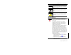
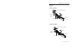
POINT I/O One-piece Terminal Bases 5 Install a Base To install a base on DIN rail, proceed as follows, referring to the figures to identify major parts of the base.
POINT I/O One-piece Terminal Bases Refer to your I/O module user manual for keying information and informatin on how to configure your module. 1. Position the base vertically above the installed units, such as an adapter, power supply, or existing module. 2. Slide the base down, allowing the interlocking side pieces to engage the adjacent installed unit. 3. Press firmly to seat the base on the DIN rail until the base snaps into place. 4.
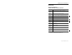
POINT I/O One-piece Terminal Bases 7 Specifications One-piece Terminal Bases 1734-TOP, 1734-TOPS, 1734-TOP3, 1734-TOP3S Attribute Value Dimensions (HxWxD), Approx. 1734-TOP, 1734-TOPS 49 x 12 x 144 mm (1.93 x 0.47 x 5.67 in.) 1734-TOP3, 1734-TOP3S 49 x 12 x 168 mm (1.93 x 0.47 x 6.61 in.) Weight, Approx. 1734-TOP 63.8 g (2.25 oz), 1734-TOP3 79.2 g (2.79 oz), 1734-TOPS 55.68 g (1.96 oz), 1734-TOP3S 66.8 g (2.36 oz) Wire Size 0.25... 2.5 mm² (22...
POINT I/O One-piece Terminal Bases Environmental Specifications Attribute Value Temperature, operating IEC 60068-2-1 (Test Ad, Operating Cold), IEC 60068-2-2 (Test Bd, Operating Dry Heat), IEC 60068-2-14 (Test Nb, Operating Thermal Shock): -20…60 °C (-4…140 °F) Temperature, nonoperating IEC 60068-2-1 (Test Ab, Unpackaged Nonoperating Cold), IEC 60068-2-2 (Test Bb, Unpackaged Nonoperating Dry Heat), IEC 60068-2-14 (Test Na, Unpackaged Nonoperating Thermal Shock): -40…85 °C (-40…185 °F) Relative hum
POINT I/O One-piece Terminal Bases 9 Notes: Publication 1734-IN028B-EN-P - April 2010
POINT I/O One-piece Terminal Bases Notes: Publication 1734-IN028B-EN-P - April 2010
POINT I/O One-piece Terminal Bases 11 Notes: Publication 1734-IN028B-EN-P - April 2010
Allen-Bradley, POINT I/O, and Rockwell Automation are trademarks of Rockwell Automation, Inc. Trademarks not belonging to Rockwell Automation are property of their respective companies. Publication 1734-IN028B-EN-P - April 2010 Supersedes Publication 1734-IN028A-EN-P - February 2006 Copyright © 2010 Rockwell Automation, Inc. All rights reserved. PN 75026 Printed in the U.S.