POINT I/O Synchronous Serial Interface Absolute Encoder Module 1734-SSI User Manual
Important User Information Solid state equipment has operational characteristics differing from those of electromechanical equipment. Safety Guidelines for the Application, Installation and Maintenance of Solid State Controls (Publication SGI-1.1 available from your local Rockwell Automation sales office or online at http://literature.rockwellautomation.com/) describes some important differences between solid state equipment and hard-wired electromechanical devices.
Summary of Changes This publication contains new and revised information not in the last release. New and Revised Information See the table for a summary of the major changes in this manual. Chapter Change Chapter 4 Set and Operate Your Module Updated section on operation of the Data Latch and Comparator features. Chapter 5 Diagnose Problems Added a column on recommended actions in all of the troubleshooting charts.
Summary of Changes 2 Notes: Publication 1734-UM007D-EN-P - December 2005
Table of Contents Preface Purpose of This Manual. . . . . . . . . . . . . . . . . . . . . . . Preface-1 Who Should Use This Manual . . . . . . . . . . . . . . . . . . Preface-1 Related Products and Documentation. . . . . . . . . . . . . Preface-2 Chapter 1 Install the Module About This Chapter . . . . . . . . . . . . . . About the Module . . . . . . . . . . . . . . . Install the Mounting Base . . . . . . . . . Install a Module . . . . . . . . . . . . . . . .
Table of Contents 2 Appendix A Configure Modules in RSLogix 5000 Software Index Publication 1734-UM007D-EN-P - December 2005 About This Appendix . . . . . . . . . . . . . . . . . . . . . . . . . . . . Understand Data, Connection, and Communication Formats Configure Your Module. . . . . . . . . . . . . . . . . . . . . . . . . . . Use the Help Button . . . . . . . . . . . . . . . . . . . . . . . . . . . . . Work with the Feedback Dialog . . . . . . . . . . . . . . . . . . . .
Preface Purpose of This Manual Who Should Use This Manual Read this manual for information about how to install, configure, and troubleshoot your module.
2 Preface Related Products and Documentation For specification, safety approval, and other information, refer to POINT I/O Synchronous Serial Interface Absolute Encoder Module Installation Instructions, publication 1734-IN581. For related 1734 products and documentation, see the table. Many of these publications are available online from http://literature.rockwellautomation.com Publication 1734-UM007D-EN-P - December 2005 Description Cat. No.
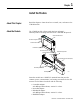
Chapter 1 Install the Module About This Chapter Read this chapter to learn about how to install, wire, and remove the 1734-SSI module. About the Module The 1734-SSI module collects serial data from industrial absolute-position encoding sensors that use a standard SSI protocol.
1-2 Install the Module Install the Mounting Base The wiring base assembly (1734-TB or 1734-TBS) consists of a mounting base (1734-MB) and a removable terminal block (1734-RTB or 1734-RTBS). You can install the assembly, or just the mounting base. To install the mounting base/wiring base assembly on the DIN rail, proceed as follows. ATTENTION POINT I/O is grounded through the DIN rail to chassis ground. Use zinc-plated yellow-chromate steel DIN rail to assure proper grounding.
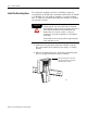
Install the Module 1-3 3. Press firmly to seat the mounting base on the DIN rail, noting that the mounting base snaps into place. M Stod ule atus Ne Stattwor us k NO DE : 0 24 So VDC Ouurce tput 1 2 3 17 OB34 4E 44013 4. To remove the mounting base from the DIN rail, remove any installed module (and any module immediately to the right), and use a small-bladed screwdriver to rotate the DIN rail locking screw to a vertical position. This releases the locking mechanism. 5.
1-4 Install the Module 1. Using a bladed screwdriver, rotate the keyswitch on the mounting base clockwise till the number required for the type of module being installed aligns with the notch in the base. 1734-SSI - Position 2 Turn the keyswitch to align the number with the notch. Notch (Position 3 Shown) 44009 2. Make sure the DIN-rail locking screw is in the horizontal position, noting that you cannot insert the module if the locking mechanism is unlocked.
Install the Module Install the Removable Terminal Block 1-5 A removable terminal block comes with your mounting base assembly. To remove, pull up on the RTB handle. This lets you remove and replace the base as necessary without removing any of the wiring. To reinsert the removable terminal block, proceed as follows. WARNING When you connect or disconnect the removable terminal block (RTB) with field-side power applied, an electrical arc can occur.
1-6 Install the Module Remove a Mounting Base To remove a mounting base, you must remove any installed module, and remove the removable terminal block (if wired). 1. Unlatch the RTB handle on the I/O module. 2. Pull on the RTB handle to remove the removable terminal block. WARNING When you connect or disconnect the removable terminal block (RTB) with field-side power applied, an electrical arc can occur. This could cause an explosion in hazardous location installations.
Install the Module Wire the Module 1-7 Read this section for information about wiring the module. WARNING If you connect or disconnect wiring while the field-side power is on, an electrical arc can occur. This could cause an explosion in hazardous location installations. Be sure that power is removed or the area is nonhazardous before proceeding.
1-8 Install the Module Module Terminations 0 D+1 1 D-1 2 V+ 3 V- 4 Shield 5 I1 6 C+1 7 C-1 1 Publication 1734-UM007D-EN-P - December 2005 D and C are RS422-type differential pairs.
Chapter 2 Configure the Module About This Chapter Read this chapter for information about how to use RSNetWorx for DeviceNet software to configure your module. You can configure the module while it is online or offline. This chapter shows configuration in the online mode. Configuration dialogs appear similar in both modes. The primary difference is that if you make changes offline, you must go online before the configuration changes take effect.
2-2 Configure the Module Add I/O Modules to Your Network After you add the communication device, you must add the POINT I/O modules connected to the scanner on the POINTBus backplane, using this procedure. 1. Add modules as shown in the figure. 1. Click here to expand the list of specialty modules. 2. Double-click the catalog number to choose the module. You can also click and drag the module name onto the network. The out-of-the-box node setting for 1734 modules is 63.
Configure the Module Set the Encoder’s Parameters 2-3 After adding the module to the network, you must configure the module for use. IMPORTANT This chapter shows configuration in the online mode. Changes set in this mode take effect when you download to the individual module. 1. Configure the modules as shown in the figure. 1. Click the module to highlight it. 2. From the Device menu, choose Properties. You can also right-click the module or name, and the property dialog pops up.
2-4 Configure the Module 2. Refer to the dialogs for an explanation of features. The module’s name appears here. Click the Device parameters tab to get to the dialog for setting the parameters. Type a description here. The module’s address appears here. (This field is read only.) This dialog also shows the module’s device identity. These fields are read only. At any point, you can click here to finish changing configuration parameters.
Configure the Module 2-5 To configure your module, select Configuration and modify the parameters as desired for your application. When complete, download to your module by clicking the Download to Device button. You can download each change as you make it using Single, or download all your changes using All. Click here when finished. Check I/O Status and View the EDS File You can view the I/O defaults setup, and the EDS file by clicking the appropriate tab.
2-6 Configure the Module Click the EDS File tab to display the statistics of the EDS file used to configure this module. Click View File to view the actual EDS file. You can view the actual EDS file or edit the file.
Chapter 3 Communicate with Your Module About This Chapter Read this chapter for information about how the 1734-SSI module transmits SSI sensor data over the DeviceNet network. About Communications Data can be exchanged with the master through a polled, cyclic, or change-of-state connection. Bit-strobe Command Response Messaging and the Unconnected Message Manager (UCMM) are not supported.
3-2 Communicate with Your Module Byte Produce 8 Produce 9 1 Bit 7 6 5 4 3 2 1 C2ST C1ST C2R C1R INC DEC RUN I1 7 6 5 4 3 2 1 0 RES RES RES LHON IDF2 CCE CCF SPF Consume 0 Consume 1 Publication 1734-UM007D-EN-P - December 2005 0 Status Byte 0 Status Byte 11 Monitor IDF to determine the validity of the produced data. If IDF=1, the SSI data is false.
Communicate with Your Module Communicate Real-time Information 3-3 The Synchronous Serial Interface Absolute Encoder module uses data bytes composed into assemblies to communicate real-time input and output data over an I/O connection, as well as non-real-time module information by using an Explicit Messaging connection. • Assembly 101 is produced data sent by the module over an I/O or Explicit Messaging connection.
3-4 Communicate with Your Module Firmware Version 4.
Communicate with Your Module 3-5 The following table shows the Instance Services provided by the Parameter Object (Attribute = 1).
3-6 Communicate with Your Module Parameter Value(1) Notes Gray to Binary Conversion No/Yes Convert data from Gray to binary SSI Word Delay Time (tm) 16µs… to 64ms (64µs) Delay time between successive SSI data words SSI Word Filter Control Off, Low, Med, High, Max Corresponds to the number of successive equal SSI data words that must be received by the module in order to update the real-time present SSI data word.
Chapter 4 Set and Operate Your Module About This Chapter Read this chapter for information about setup and operation of your module. You need to alter the 1734-SSI module configuration, special data latch feature, and comparator feature in order for the 1734-SSI module to operate properly with your SSI sensor.
4-2 Set and Operate Your Module Publication 1734-UM007D-EN-P - December 2005 Value Definition Data Rate The data rate is the SSI sensor’s communication rate (bits/s) stated in the manufacturer’s data sheet. The data rate you select at the SSI module equals the approximate frequency of the SSI module’s clock output (the actual measure frequency varies with the SSI word delay time).
Set and Operate Your Module 4-3 Value Definition Sensor Resolution The number of steps per revolution for a rotary sensor, or total number of steps per stroke for a linear or optical transducer. The Sensor Resolution value is not used by the module and is not needed for proper module operation with your SSI sensor. The Sensor Resolution value can be passed to the network master for processing if desired. The range is 1…65,535 steps and the default value is 1.
4-4 Set and Operate Your Module Operation of the Data Latch and Comparator Features Read this section for information about operation of the Data Latch and Comparator features. Data Latch See the table for a listing of values for DeviceNet name, RSLogix 5000 tag, and RSLogix 5000 field name.
Set and Operate Your Module 4-5 Comparators 1 and 2 You can store two separate four-byte values and be notified when the SSI sensor attains or exceeds the stored value. Comparators 1 and 2 are mutually exclusive: only one comparator can be active at any given time. You can set a comparator to trigger on an increasing sensor count, decreasing count, or regardless of sensor direction, by choosing Both for the comparator control value. There are two modes of comparator operation: manual and automatic.
4-6 Set and Operate Your Module Automatic Mode The purpose of the Automatic mode is to provide a means of switching between two comparator values without having to activate each comparator separately through the configuration. In Automatic mode, only the Both comparator control setting is active for Comparator 1 and Comparator 2. There is no provision to choose between the comparator control settings in Automatic mode.
Set and Operate Your Module 4-7 Major module faults are indicated by the presence of the CCF and CCE bits, bits 1 and 2 respectively of Status Byte 1.If either of these bits is 1, you do not receive correct SSI sensor data. Try resetting the module with a power cycle. If either of these bits remain ON, call technical support for further assistance.You can monitor power or major module faults by monitoring a single bit in Status Byte 1; the IDF bit (bit 3 of Status Byte 1).
4-8 Set and Operate Your Module At point B of the CLK signal is the rising clock edge. The sensor begins to send its serial data to the 1734-SSI module. The module actually starts reading the sensor position data on the next rising clock edge, denoted by MSB in the figure above. MSB is the most significant bit of the data word. The 1734-SSI module supports only MSB aligned data. This means that the SSI sensor sends the MSB of its data word first, and the least significant bit (LSB) is sent last.
Chapter 5 Diagnose Problems About This Chapter Read this chapter for information about how to troubleshoot using the module indicators. Use the Indicators for Troubleshooting Use these indicators to help you troubleshoot problems with your 1734-SSI module. Module Status Network Status Module Status Network Status NODE: RUN UP Run Up DOWN Down COMP Comp I1 I1 1734 SSI 43125 Indication Probable Cause Recommended Action Off No power applied to device. Apply power to the device.
5-2 Diagnose Problems Indication Probable Cause Recommended Action Off Device is not online. - Device has not completed dup_MAC_id test. - Device not powered - check module status indicator. Apply power to device. Flashing Green Device is online but has no connections in the established state. None - device is in Idle or Program mode. Solid Green Device is online and has connections in the established state. None Flashing Red One or more I/O connections are in timed-out state.
Appendix A Configure Modules in RSLogix 5000 Software About This Appendix Read this appendix for information about how to configure your modules in RSLogix 5000 software, including how to complete entries on the following dialogs, which are not available for Listen Only connections. • • • • Understand Data, Connection, and Communication Formats Feedback Conversion Input Registration Watch Position Before you configure your modules, note the following about Data formats and Connection types.
A-2 Configure Modules in RSLogix 5000 Software When you change Connection and Data Format, note the following. • You do not delete the existing module. • You do not create a new module. • You bring forward all possible configuration data for the new setting. • Configuration data that you cannot bring forward sets to the default value. Once you apply new settings, this becomes the base configuration for the next change in Connection and Data Format settings.
Configure Modules in RSLogix 5000 Software Work with the Feedback Dialog A-3 Follow these procedures to complete entries for the Feedback dialog. 1. From the General dialog, click Feedback to display the Feedback dialog. 2. From the Feedback dialog, complete entries, referring to the table. 3. From the Feedback dialog, complete one of these. • Click OK to save changes and close the dialog. or • Click Cancel to return to default values.
A-4 Configure Modules in RSLogix 5000 Software For Select Comments Code Type Binary or Gray Default is Gray. Word Length 2…31 Default is 13. Data Speed 125 Kbps 250 Kbps 500 Kbps 1 MBps 2 MBps Default is 125 Kbps. SSI Word Delay Time 16…65535 Default is 64 µs. SSI Word Filter Control Max High Med Low Off Default is Max. SSI Clock Select On or Off to select the SSI clock. For more information on these parameters refer to the definitions in Chapter 4 of this publication.
Configure Modules in RSLogix 5000 Software A-5 3. From the Conversion dialog, complete one of these. • Click OK to save changes and close the dialog. or • Click Cancel to return to default values. or • Click Apply to save changes you made on any of the dialogs and continue to display the dialog, noting that you enable the Apply button when you make changes to any of the dialogs. or • Click another tab at the top of dialog.
A-6 Configure Modules in RSLogix 5000 Software Work with the Input Registration Dialog Follow these procedures to complete the Input Registration dialog. 1. From the General dialog, click Input Registration to display the dialog. 2. From the Input Registration dialog for Input Latch select one of these, with Off being the default. • Off • Off-to-On • On-to-Off • Both Edges 3. From the Input Registration dialog, complete one of these. • Click OK to save changes and close the dialog.
Configure Modules in RSLogix 5000 Software Work with the Watch Position Dialog A-7 Follow these procedures to complete the entries for the Watch Position dialog, refering to the Comparators 1 and 2 section of the Set and Operate Your Module chapter for a description of: • Comparator Control and Comparator Value • Manual and Automatic mode 1. From the General dialog, click Watch Position to display the Watch Position dialog with the Not Active default for Comparator Control 0 and 1.
A-8 Configure Modules in RSLogix 5000 Software 2. From the Watch Position dialog, make entries for Automatic or Manual mode, refering to the table and noting the following. • For Automatic mode for Comparator Control 0 and 1, leave the value as Not Active and complete the entries for Comparator Value 0 and 1. • For Manual mode, click a value for Comparator Control 0 and 1 and complete entries for Comparator Value 0 and 1, noting that in the figure the value shows Up Direction for Comparator Control 0.
Index Numerics 1734-SSI module about 1-1 24-bit SSI sensor 4-7 A adapters ControlNet 1-1 DeviceNet 1-1 Ethernet/IP 1-1 PROFIBUS 1-1 add adapter to network 2-1 I/O modules to network 2-2 automatic mode comparator operation 4-6 E EDS file Preface-1, 2-5 example use of 1734-SSI module with a 24-bit SSI sensor 4-7 F feedback dialog A-3 formats communication A-1 data A-1 H help button A-2 I B base assembly mounting 1-2 bit and byte definitions 3-1 C checking I/O defaults 2-5 commissioning a node 2-2 compar
2 Index SSI word filter control 4-2 SSI Word Length 4-1 trailing bits 4-2 module installation 1-3 monitor major module faults 4-7 power 4-7 mounting base assembly 1-2 mounting base removal 1-6 N node commissioning tool 2-2 node setting (out of box) 2-2 P parameter setting 2-3 positioning the keyswitch 1-4 produced bit and byte definitions 3-1 installation 1-5 RSLogix 5000 software 1-1, A-1 RSNetWorx for DeviceNet software 2-1 S setting module parameters 2-3 software RSLogix 5000 1-1, A-1 RSNetworx for
How Are We Doing? Your comments on our technical publications will help us serve you better in the future. Thank you for taking the time to provide us feedback. You can complete this form and mail (or fax) it back to us or email us at RADocumentComments@ra.rockwell.com Pub. Title/Type POINT I/O Synchronous Serial Interface Absolute Encoder Module Cat. No. 1734-SSI Pub. No. 1734-UM007D-EN-P Pub. Date December 2005 Part No. 957988-74 Please complete the sections below.
PLEASE FASTEN HERE (DO NOT STAPLE) PLEASE FOLD HERE NO POSTAGE NECESSARY IF MAILED IN THE UNITED STATES BUSINESS REPLY MAIL FIRST-CLASS MAIL PERMIT NO.
Rockwell Automation Support Rockwell Automation provides technical information on the web to assist you in using its products. At http://support.rockwellautomation.com, you can find technical manuals, a knowledge base of FAQs, technical and application notes, sample code and links to software service packs, and a MySupport feature that you can customize to make the best use of these tools.