Installation Instructions POINT I/O DeviceNet Communication Interface Module Catalog Number 1734-PDN, Series B Inside… For This Topic See Page Important User Information 2 Preventing Electrostatic Discharge 3 Environment and Enclosure 4 Identify Module Components 5 Install the Module 6 Install the Module in an Existing System 7 Wire the Module 8 Troubleshoot with Indicators 12 North American Hazardous Location Approval 13 European Hazardous Location Approval 14 Specifications 15 Ro
POINT I/O DeviceNet Communication Interface Module Important User Information Solid state equipment has operational characteristics differing from those of electromechanical equipment. Safety Guidelines for the Application, Installation and Maintenance of Solid State Controls (Publication SGI-1.1 available from your local Rockwell Automation sales office or online at http://literature.rockwellautomation.
POINT I/O DeviceNet Communication Interface Module 3 ATTENTION Preventing Electrostatic Discharge This equipment is sensitive to electrostatic discharge, which can cause internal damage and affect normal operation. Follow these guidelines when you handle this equipment: • Touch a grounded object to discharge potential static. • Wear an approved grounding wriststrap. • Do not touch connectors or pins on component boards. • Do not touch circuit components inside the equipment.
POINT I/O DeviceNet Communication Interface Module ATTENTION Environment and Enclosure This equipment is intended for use in a Pollution Degree 2 industrial environment, in overvoltage Category II applications (as defined in IEC publication 60664-1), at altitudes up to 2000 meters without derating. This equipment is considered Group 1, Class A industrial equipment according to IEC/CISPR Publication 11.
POINT I/O DeviceNet Communication Interface Module 5 POINT I/O is grounded through the DIN rail to chassis ground. Use zinc plated yellow-chromate steel DIN rail to assure proper grounding. The use of other DIN rail material (e.g., aluminum, plastic, etc.) that can corrode, oxidize, or are poor conductors, can result in improper or intermittent grounding. Secure DIN rail to mounting surface approximately every 200 mm.
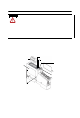
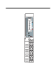
POINT I/O DeviceNet Communication Interface Module Install the Module To install the module on the DIN rail, proceed as follows. ATTENTION When you insert or remove the module while backplane power is on, an electrical arc can occur. This could cause an explosion in hazardous location installations. Be sure that power is removed or the area is nonhazardous before proceeding. Repeated electrical arcing causes excessive wear to contacts on both the module and its mating connector.
POINT I/O DeviceNet Communication Interface Module 7 Install the Module in an Existing System To install a replacement module in an existing system, proceed as follows. 1. To remove the module from the DIN rail, pull up on the RTB removal handle to remove the terminal block. WARNING When you connect or disconnect the Removable Terminal Block (RTB) with field-side power applied, an electrical arc can occur. This could cause an explosion in hazardous location installations.
POINT I/O DeviceNet Communication Interface Module Wire the Module WARNING If you connect or disconnect wiring while the field-side power is on, an electrical arc can occur. This could cause an explosion in hazardous location installations. Be sure that power is removed or the area is nonhazardous before proceeding. .
POINT I/O DeviceNet Communication Interface Module 9 DeviceNet Connector System Power DeviceNet Power NC CHAS GND NC CHAS GND C C V V NC = No Connection CHAS GND = Chassis Ground C = Common V = Supply 42513 Publication 1734-IN057D-EN-P - April 2005
POINT I/O DeviceNet Communication Interface Module 12/24V dc Wiring 0 1 NC NC 2 3 CHAS CHAS GND GND 12/24V dc Power 4 5 C C V V Connect this supply to the internal field-power bus. V dc 6 7 43960 NC = No Connection C = Common CHAS GND = Chassis Ground V = Supply Connect Terminal In Terminal Out +V dc 6 7 -V dc 4 5 Chas Gnd 2 3 12/24V dc becomes the internal field-power bus for modules to the right.
POINT I/O DeviceNet Communication Interface Module 11 120/240V ac Wiring 0 2 120/240V ac 1 NC NC CHAS GND CHAS GND 4 5 L2/N L2/N V ac 3 6 Connect this supply to the internal field-power bus. 7 L1 L1 NC = No Connection L2/N = Neutral, L1 = 120/240V ac CHAS GND = Chassis Ground 43961 Connect Terminal In Terminal Out L1 6 7 L2/N 4 5 Chas Gnd 2 3 120/240V ac becomes the internal field-power bus for modules to the right.
POINT I/O DeviceNet Communication Interface Module Troubleshoot with Indicators Use the status indicators to troubleshoot your module. System Power DeviceNet Power 41970 Indicator Indication Probable Cause System Power Off Not active DeviceNet power is off or DC-DC converter problem. Green System power is on. DC-DC converter is active (5V). Off Not active DeviceNet power is OFF. Green Power is on with 24V present.
POINT I/O DeviceNet Communication Interface Module 13 North American Hazardous Location Approval The following information applies when operating this equipment in hazardous locations: Informations sur l’utilisation de cet équipement en environnements dangereux: Products marked “CL I, DIV 2, GP A, B, C, D” are suitable for use in Class I Division 2 Groups A, B, C, D, Hazardous Locations and nonhazardous locations only.
POINT I/O DeviceNet Communication Interface Module European Hazardous Location Approval European Zone 2 Certification (The following applies when the product bears the EEx marking.) This equipment is intended for use in potentially explosive atmospheres as defined by European Union Directive 94/9/EC.
POINT I/O DeviceNet Communication Interface Module 15 Specifications Communication Interface Specifications Expansion I/O Capacity Up to 17 modules, dependent on backplane bus current draw (17 times 75mA = 1.275A, just under the limit of 1.3A) The actual number of modules can vary. Add up the current requirements of the modules you want to use to make sure they do not exceed the amperage limit of the 1734-PDN module. Cat. No.
POINT I/O DeviceNet Communication Interface Module Communication Interface Specifications (continued) Communication Rate 125K bit/s (500m maximum) 250K bit/s (250m maximum) 500K bit/s (100m maximum) DeviceNet Power Requirements 24V dc (+4% = 25V dc max) @ 400mA maximum DeviceNet Cable Allen-Bradley part number 1485C-P1-Cxxx Refer to publication NETS-SG001 for more information.
POINT I/O DeviceNet Communication Interface Module 17 General Specifications POINTBus Output Current 1.3A maximum @5V dc +5% (4.75...5.25) Power Consumption 8.0W @25V dc Power Dissipation 1.2W maximum @ 25V dc Thermal Dissipation 4.1 BTU per hour, maximum @ 25V dc Isolation Voltage (continuous-voltage withstand rating) 50V continuous Tested to withstand 2600V dc for 60s Field Power Bus Supply Current Supply Voltage Dimensions Inches (Millimeters) Operating Temperature 10A maximum 10...28.
POINT I/O DeviceNet Communication Interface Module Radiated RF Immunity IEC 61000-4-3 10V/m with 1KHz sine-wave 80%AM from 30MHz to 2000MHz 10V/m with 200Hz 50% Pulse 100%AM at 900MHz 10V/m with 200Hz 50% Pulse 100%AM at 1890 MHz EFT/B Immunity IEC 61000-4-4 +4kV at 2.
POINT I/O DeviceNet Communication Interface Module 19 Certification2 (when product is marked) c-UL-us UL Listed Industrial Control Equipment, certified for U.S. and Canada c-UL-us UL Listed for Class I, Division 2, Group A,B,C,D Hazardous Locations, certified for U.S. and Canada CE European Union 89/336/EEC EMC Directive, compliant with: EN 50082-2; Industrial Immunity EN 61326; Meas./Control/Lab.
Rockwell Automation Support Rockwell Automation provides technical information on the web to assist you in using its products. At http://support.rockwellautomation.com, you can find technical manuals, a knowledge base of FAQs, technical and application notes, sample code and links to software service packs, and a MySupport feature that you can customize to make the best use of these tools.