Installation Instructions POINT I/O 2 Relay Output Module (Cat. No.
POINT I/O 2 Relay Output Module This Series C product can be used with DeviceNet and PROFIBUS adapters. It can be used with ControlNet and Ethernet adapters using RSLogix 5000, version 11 (or higher) software.
POINT I/O 2 Relay Output Module WARNING ! ATTENTION ! IMPORTANT 3 Identifies information about practices or circumstances that can cause an explosion in a hazardous environment, which may lead to personal injury or death, property damage, or economic loss. Identifies information about practices or circumstances that can lead to personal injury or death, property damage, or economic loss. Identifies information that is critical for successful application and understanding of the product.
POINT I/O 2 Relay Output Module ATTENTION ! Environment and Enclosure This equipment is intended for use in a Pollution Degree 2 industrial environment, in overvoltage Category II applications (as defined in IEC publication 60664-1), at altitudes up to 2000 meters without derating. This equipment is considered Group 1, Class A industrial equipment according to IEC/CISPR Publication 11.
POINT I/O 2 Relay Output Module WARNING ! ATTENTION ! 5 EXPLOSION HAZARD • Do not disconnect equipment unless power has been removed or the area is known to be nonhazardous. • Do not disconnect connections to this equipment unless power has been removed or the area is known to be nonhazardous. Secure any external connections that mate to this equipment by using screws, sliding latches, threaded connectors, or other means provided with this product.
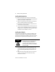
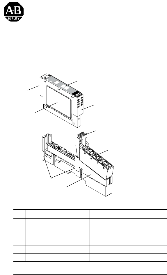
POINT I/O 2 Relay Output Module Installing the Mounting Base To install the mounting base on the DIN rail, proceed as follows. 1. Position the mounting base vertically above the installed units (adapter, power supply or existing module. 2. Slide the mounting base down allowing the interlocking side pieces to engage the adjacent module or adapter. 3. Press firmly to seat the mounting base on the DIN rail. The mounting base will snap into place. 4.
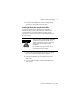
POINT I/O 2 Relay Output Module 7 3. Insert the module straight down into the mounting base and press to secure. The module will lock into place. Installing the Removable Terminal Block (RTB) A removable terminal block is supplied with your wiring base assembly. To remove, pull up on the RTB handle. This allows the mounting base to be removed and replaced as necessary without removing any of the wiring. To reinsert the removable terminal block, proceed as follows.
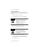
POINT I/O 2 Relay Output Module Removing a Mounting Base To remove a mounting base, you must remove any installed module, and the module installed in the base to the right. Remove the removable terminal block (if wired). 1. Unlatch the RTB handle on the I/O module. 2. Pull on the RTB handle to remove the removable terminal block. WARNING ! When you connect or disconnect the Removable Terminal Block (RTB) with field side power applied, an electrical arc can occur.
POINT I/O 2 Relay Output Module 9 Communicating with Your Module I/O messages are sent to (consumed) and received from (produced) the POINT I/O modules. These messages are mapped into the processor’s memory. This POINT I/O output module does not produce input data (scanner Rx). It does consume 1 byte of I/O data (scanner Tx).
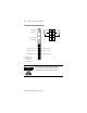
POINT I/O 2 Relay Output Module Wiring the Relay Output Module Module Status Module Status Network Status Network Status 0 1 2 3 4 5 6 7 NODE: Relay Output Status of Output 0 0 Status of Output 1 1 1734 OX2 Output 0 Connection - NC NC - Output 1 Connection Output 0 Connection - NO NO - Output 1 Connection Output 0 Relay Common - RC NC = Normally closed NO = Normally open RC = Relay Common +V = Positive Supply ATTENTION ! +V RC - Output 1 Relay Common +V 41974 Relay contacts
POINT I/O 2 Relay Output Module 11 Load powered by Internal Power Bus 1 0 Out 0 NC 2 Load L2/N Out 0 NO 4 Out 0 L1 Out 1 NC Out 1 NO 3 RC Out 1 5 RC +V +V 6 L2/N Load 7 L1 NC = Normally closed NO = Normally open RC = Relay Common +V = Positive Supply 42019OX Channel Output 0 (N.C.) 0 0 (N.O.) 2 1 (N.C.) 1 1 (N.O.) 3 Relay Common Supply 4 6 5 7 Supply voltage can range from +5V dc to 240V ac, depending on relay load.
POINT I/O 2 Relay Output Module Load powered by External Power Bus L1 Power Supply 0 1 Out 0 NC Out 1 NC 2 L2/N Out 0 NO Out 1 NO Out 0 RC Out 1 RC 4 Load 6 +V Power Supply L1 3 L2/N 5 Load 7 +V Out = Output channel relay contacts Power Supply = can range from +5V dc to 240V ac RC = Relay Common Channel Output 0 (N.C.) 0 0 (N.O.) 2 1 (N.C.) 1 1 (N.O.
POINT I/O 2 Relay Output Module ATTENTION • Do not attempt to increase load current or wattage capability beyond the maximum rating by connecting 2 or more outputs in parallel. The slightest variation in relay switching time may cause one relay to momentarily switch the total load current. • Make certain that all relay wiring is properly connected before applying any power to the module. • Total current draw through the wiring base unit is limited to 10A.
POINT I/O 2 Relay Output Module PDN IB2 0 24V 1 0 IB4 1 0 IV2 IV4 1 0 1 0 OX2 1 0 L2/N 1 OX2 OX2 0 0 1 1 L1 120V/240V ac Wiring using external power source for ac Relay power Publication 1734-IN587B-EN-P - March 2002 42010lt
POINT I/O 2 Relay Output Module 15 Troubleshooting with the Indicators Module Status Module Status Network Status Network Status NODE: Relay Output Status of Output 0 0 Status of Output 1 1 1734 OX2 Output 0 NC Connection Output 1 NC Connection Output 0 NO Connection Output 1 NO Connection Output 0 Relay Common Output 1 Relay Common +V +V 41974 Module Status Off No power applied to device Green Device operating normally Flashing Green Device needs commissioning due to configuration m
POINT I/O 2 Relay Output Module Indicator Indication Probable Cause Network Status Indicator Off Device is not on-line - Device has not completed dup_MAC_id test. - Device not powered - check module status indicator Flashing Green Device is on-line but has no connections in the established state. Green Device on-line and has connections in the established state. Flashing Red One or more I/O connections in timed-out state Red Critical link failure - failed communication device.
POINT I/O 2 Relay Output Module 17 Safety Approvals The following information applies when operating this equipment in hazardous locations: Informations sur l’utilisation de cet équipement en environnements dangereux: Products marked “CL I, DIV 2, GP A, B, C, D” are suitable for use in Class I Division 2 Groups A, B, C, D, Hazardous Locations and nonhazardous locations only. Each product is supplied with markings on the rating nameplate indicating the hazardous location temperature code.
POINT I/O 2 Relay Output Module Specifications Specifications - 1734-OX2 Output Relay Module Outputs per Module 2 Form C isolated (normally open; normally closed) electromechanical relays Off-State Leakage Current (max at 240V ac) 2.0mA and bleed resistor thru snubber circuit Output Voltage Range (load dependent) 5-28.8V dc @ 2.0A resistive 48V dc @ 0.5A resistive 125V dc @ 0.25A resistive 125V ac @ 2.0A resistive 240V ac @ 2.
POINT I/O 2 Relay Output Module 19 Fusing Module outputs are not fused. If fusing is desired, you must supply external fusing. Indicators 2 green/red module/network status 2 yellow output status Keyswitch position 7 General Specifications Module Location 1734-TB or -TBS wiring base assembly Pointbus Current 100mA max @ 5V dc Power Dissipation 0.5W max Thermal Dissipation 1.
EFT/B Immunity IEC 61000-4-4: ±2kV at 5kHz on signal ports Surge Transient Immunity IEC 61000-4-5: ±1kV line-line(DM) and ±2kV line-earth(CM) on signal ports Conducted RF Immunity IEC 61000-4-6: 10Vrms with 1kHz sine-wave 80%AM from 150kHz to 80MHz Emissions CISPR 11; Group 1, Class A Enclosure Type Rating None (open-style) Conductors 14 AWG (2.5mm2) - 22 AWG (0.25mm2) solid or stranded copper wire rated @ 75°C or greater 3/64 inch (1.