
Owner manual


POINT I/O 2 and 4 Relay Output Modules 13
Publication 1734-IN055F-EN-E - March 2012
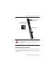
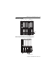
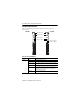
6. Use a small bladed screwdriver to rotate the orange base locking screw to a
vertical position. This releases the locking mechanism.
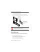
7. Lift straight up to remove.
Communicate with Your Module
I/O messages are sent to (consumed) and received from (produced) the POINT I/O
modules. These messages are mapped onto the processor’s memory.
This POINT I/O output module does not produce input data (scanner Rx). It consumes
1 Byte of I/O data (scanner Tx).
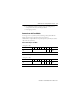
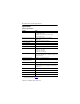
Default Data Map for 1734-OW2
Message size: 1 Byte
76543210
Consumes (scanner
Tx)
Not used Ch
1
Ch
0
Channel
state
Where: 0 = Off, 1 = On
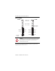
Default Data Map for 1734-OW4
Message size: 1 Byte
76543210
Consumes (scanner
Tx)
Not used
Ch3 Ch2
Ch
1
Ch
0
Channel
state
Where: 0 = Off, 1 = On