Installation Instructions POINT I/O 2 and 4 Relay Output Modules Catalog numbers 1734-OW2, 1734-OW4, Series C Table of Contents Topic Page Important User Information 2 Environment and Enclosure 3 Preventing Electrostatic Discharge 3 North American Hazardous Location Approval 5 Additional Resources 6 About the Module 7 Mount the I/O Base 9 Install the Module 10 Install the Removable Terminal Block 11 Remove a Mounting Base 12 Communicate with Your Module 13 Wire the Module 14 Inter
POINT I/O 2 and 4 Relay Output Modules Important User Information Solid-state equipment has operational characteristics differing from those of electromechanical equipment. Safety Guidelines for the Application, Installation and Maintenance of Solid State Controls (Publication SGI-1.1 available from your local Rockwell Automation sales office or online at http://www.rockwellautomation.
POINT I/O 2 and 4 Relay Output Modules 3 Environment and Enclosure ATTENTION: This equipment is intended for use in a Pollution Degree 2 industrial environment, in overvoltage Category II applications (as defined in IEC 60664-1), at altitudes up to 2000 m (6562 ft) without derating. This equipment is considered Group 1, Class A industrial equipment according to IEC/CISPR 11.
POINT I/O 2 and 4 Relay Output Modules European Hazardous Location Approval European Zone 2 Certification (The following applies when the product bears the Ex Marking) This equipment is intended for use in potentially explosive atmospheres as defined by European Union Directive 94/9/EC.
POINT I/O 2 and 4 Relay Output Modules 5 North American Hazardous Location Approval The following information applies when operating this equipment in hazardous locations: Informations sur l’utilisation de cet équipement en environnements dangereux: Products marked "CL I, DIV 2, GP A, B, C, D" are suitable for use in Class I Division 2 Groups A, B, C, D, Hazardous Locations and nonhazardous locations only.
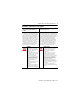
POINT I/O 2 and 4 Relay Output Modules Additional Resources These documents contain additional information concerning related Rockwell Automation products. Resource Description 1769-L32E and 1769-L35E CompactLogix Controller Installation Instructions, publication 1768-IN020. Provides details on how to assemble and mount the controller, how to upgrade firmware, and controller technical specifications. 1769-L32C and 1769-L35CR CompactLogix Controller Installation Instructions, publication 1769-IN070.
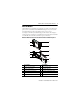
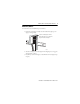
POINT I/O 2 and 4 Relay Output Modules 7 About the Module These POINT™ I/O 2 and 4 Relay Output Modules, 1734-OW2, 1734-OW4, Series C products can be used with DeviceNet and PROFIBUS adapters. They can be used with ControlNet and Ethernet adapters using RSLogix 5000, version 11 or later. See the figures to familiarize yourself with major parts of the modules.
POINT I/O 2 and 4 Relay Output Modules Modules Mounted on 1734-TOP or 1734-TOPS One-piece Terminal Base 1 6 2 3 7 4 5 8 45712 Description Description 1 Module locking mechanism 5 2 Module wiring diagram 6 Slide-in writable label 3 DIN rail locking screw (orange) 7 Handle 4 Mechanical keying 8 1734-TOP or 1734-TOPS one-piece terminal base with screw or spring clamp Publication 1734-IN055F-EN-E - March 2012 Interlocking side pieces
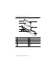
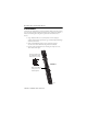
POINT I/O 2 and 4 Relay Output Modules 9 Mount the I/O Base To mount the I/O base on the DIN rail, proceed as follows: 1. Position the mounting base vertically above the installed units (adapter, power supply or existing module). Slide the mounting base until the interlocking side pieces engage the adjacent module or adapter. 31586 2. Slide the mounting base down allowing the interlocking side pieces to engage the adjacent module or adapter. 3. Press firmly to seat the mounting base on the DIN rail.
POINT I/O 2 and 4 Relay Output Modules Install the Module The module can be installed before or after base installation. Make sure that the mounting base is correctly keyed before installing the module into the mounting base. In addition, make sure the mounting base locking screw is positioned horizontal in reference to the base. 1.
POINT I/O 2 and 4 Relay Output Modules 11 Make sure the DIN-rail locking screw is in the horizontal position. Turn the keyswitch to align the number with the notch. Notch position 1 is shown. 1734-TOP Base 45697 WARNING: When you insert or remove the module while backplane power is on, an electrical arc can occur. This could cause an explosion in hazardous location installations. Be sure that power is removed or the area is nonhazardous before proceeding.
POINT I/O 2 and 4 Relay Output Modules 1. Insert the end opposite the handle into the base unit. This end has a curved section that engages with the wiring base. 2. Rotate the terminal block into the wiring base until it locks itself in place. 3. If an I/O module is installed, snap the RTB handle into place on the module.
POINT I/O 2 and 4 Relay Output Modules 13 6. Use a small bladed screwdriver to rotate the orange base locking screw to a vertical position. This releases the locking mechanism. 7. Lift straight up to remove. Communicate with Your Module I/O messages are sent to (consumed) and received from (produced) the POINT I/O modules. These messages are mapped onto the processor’s memory. This POINT I/O output module does not produce input data (scanner Rx). It consumes 1 Byte of I/O data (scanner Tx).
POINT I/O 2 and 4 Relay Output Modules Wire the Module 1734-OW2 Module Status Module status Network status Network Status NODE: Module Status 1734-OW4 Network Status NODE: Relay Output Relay Output Status of output 0 Status of output 1 0 1 0 1 Status of output 2 Status of output 3 2 3 1734 OW2 1734 OW4 Output 0A Output 1A Output 0A Output 1A Output 0B Output 1B Output 0B Output 1B C C Output 2A Output 3A V V Output 2B Output 3B C = Common V = Supply 45183 45184 WARNING:
POINT I/O 2 and 4 Relay Output Modules 15 1734-OW2 – Load Powered by Internal Power Bus 0 1 Out 0A Out 1A 2 3 Out 0B Out 1B Out = Output channel relay contacts V = Supply (ranges from 5V DC…240V AC) C = Common Load 4 5 C C V V 6 Load 7 1734-OW4 – Load Powered by External Power Bus Power supply 0 Load Out = Output channel relay contacts Power supply 1 Out 0A Out 1A Power supply 2 3 Load Out 0B Out 1B 4 Power supply 5 Out 2A Out 3A Load 6 7 Load Out 2B Out 3B Load power mus
POINT I/O 2 and 4 Relay Output Modules ATTENTION: The power supply voltage may be daisychained from a 1734 adapter, 1734-FPD or 1734-EP24DC communication interface. Each channel is individually isolated and may have a unique supply and/or voltage as necessary. ATTENTION: Do not attempt to increase load current or wattage capability beyond the maximum rating by connecting two or more outputs in parallel.
POINT I/O 2 and 4 Relay Output Modules 17 Wire Using a 1734-FPD IB2 PDN IB4 IV2 IV4 OW2 OW2 OW2 FPD 0 1 0 1 0 1 0 1 0 1 0 1 0 1 0 1 0 1 2 3 2 3 2 3 2 3 2 3 2 3 2 3 2 3 2 3 4 5 4 5 4 5 4 5 4 5 4 5 4 5 4 5 4 5 6 7 6 7 6 7 6 7 6 7 6 7 6 7 6 7 6 7 AC power bus 45187 L2/N L1 CV Wire Using External Power Source for AC Relay Power IB2 PDN IB4 IV2 OW2 OW2 IV4 OW2 0 1 0 1 0 1 0 1 0 1 0 1 0 1 0 2 3 2 3 2 3 2
POINT I/O 2 and 4 Relay Output Modules Interpret Status Indicators Refer to the following diagram and table for information on how to interpret the status indicators.
POINT I/O 2 and 4 Relay Output Modules 19 Indicator Status for Modules Network status Status Off Flashing green Green Flashing red Red Flashing red/green I/O status Off Yellow Description Device is not online: - Device has not completed dup_MAC-id test. - Device not powered – check module status indicator. Device is online but has no connections in the established state. Device is online and has connections in the established state. One or more I/O connections are in timed-out state.
POINT I/O 2 and 4 Relay Output Modules Specifications General Specifications Attribute Value Outputs per module 1734-OW2 – 2 Form A isolated (normally open) electromechanical relays 1734-OW4 – 4 Form A isolated (normally open) electromechanical relays Off-state leakage current, max 1.2 A @ 240V AC, and bleed resistor through snubber circuit Terminal base screw torque Determined by installed terminal block Power consumption 0.8 W Power dissipation, max 0.
POINT I/O 2 and 4 Relay Output Modules 21 Environmental Specifications Attribute Value Temperature, operating IEC 60068-2-1 (Test Ad, Operating Cold), IEC 60068-2-2 (Test Bd, Operating Dry Heat), IEC 60068-2-14 (Test Nb, Operating Thermal Shock): -20…55 °C (-4…131 °F) Temperature, surrounding air, max.
POINT I/O 2 and 4 Relay Output Modules Certifications Certification (when product is marked)(1) Value c-UL-us UL Listed Industrial Control Equipment, certified for US and Canada. See UL File E65584. UL Listed for Class I, Division 2 Group A,B,C,D Hazardous Locations, certified for U.S. and Canada. See UL File E194810 CE European Union 2004/108/EC EMC Directive, compliant with: EN 61326-1; Meas./Control/Lab.
POINT I/O 2 and 4 Relay Output Modules 23 Publication 1734-IN055F-EN-E - March 2012
Rockwell Automation Support Rockwell Automation provides technical information on the Web to assist you in using its products. At http://www.rockwellautomation.com/support/, you can find technical manuals, a knowledge base of FAQs, technical and application notes, sample code and links to software service packs, and a MySupport feature that you can customize to make the best use of these tools.