Installation Instructions POINT I/O Protected Sink Output Module Catalog Numbers 1734-OV2E, 1734-OV4E, and 1734-OV8E Series C Inside . . .
POINT I/O Protected Sink Output Module Important User Information Solid state equipment has operational characteristics differing from those of electromechanical equipment. Safety Guidelines for the Application, Installation and Maintenance of Solid State Controls (Publication SGI-1.1 available from your local Rockwell Automation sales office or online at http://www.literature.rockwellautomation.
POINT I/O Protected Sink Output Module 3 Prevent Electrostatic Discharge ATTENTION This equipment is sensitive to electrostatic discharge, which can cause internal damage and affect normal operation. Follow these guidelines when you handle this equipment: • Touch a grounded object to discharge potential static. • Wear an approved grounding wriststrap. • Do not touch connectors or pins on component boards. • Do not touch circuit components inside the equipment. • Use a static-safe workstation if available.
POINT I/O Protected Sink Output Module Environment and Enclosure ATTENTION This equipment is intended for use in a Pollution Degree 2 industrial environment, in overvoltage Category II applications (as defined in IEC publication 60664-1), at altitudes up to 2000 meters without derating. This equipment is considered Group 1, Class A industrial equipment according to IEC/CISPR Publication 11.
POINT I/O Protected Sink Output Module 5 North American Hazardous Location Approval The following information applies when operating this equipment in hazardous locations: Informations sur l’utilisation de cet équipement en environnements dangereux: Products marked “CL I, DIV 2, GP A, B, C, D” are suitable for use in Class I Division 2 Groups A, B, C, D, hazardous locations and nonhazardous locations only.
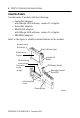
POINT I/O Protected Sink Output Module About the Module Use this series C module with the following: • ControlNet adapters with RSLogix 5000 software, version 11 or higher • DeviceNet adapters • EtherNet/IP adapters with RSLogix 5000 software, version 11 or higher • PROFIBUS adapters Refer to the figure to identify external features of the module.
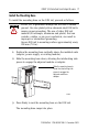
POINT I/O Protected Sink Output Module 7 Install the Mounting Base To install the mounting base on the DIN rail, proceed as follows. ATTENTION POINT I/O is grounded through the DIN rail to chassis ground. Use zinc-plated yellow-chromate steel DIN rail to assure proper grounding. The use of other DIN rail material (for example, aluminum and plastic) that can corrode, oxidize, or are poor conductors, can result in improper or intermittent grounding.
POINT I/O Protected Sink Output Module Install the Module ATTENTION When you insert or remove the module while backplane power is on, an electrical arc can occur. This could cause an explosion in hazardous location installations. Be sure that power is removed or the area is nonhazardous before proceeding. Repeated electrical arcing causes excessive wear to contacts on both the module and its mating connector. Worn contacts may create electrical resistance that can affect module operation.
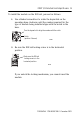
POINT I/O Protected Sink Output Module 9 To install the module on the DIN rail, proceed as follows. 1. Use a bladed screwdriver to rotate the keyswitch on the mounting base clockwise until the number required for the type of module being installed aligns with the notch in the base. Turn the keyswitch to align the number with the notch. Notch (position 3 shown) 44009 2. Be sure the DIN rail locking screw is in the horizontal position. Make sure the DIN rail locking screw is in the horizontal position.
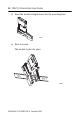
POINT I/O Protected Sink Output Module M Sta od tu ule s 3 1 O 73 B 4 4E 2 1 0 24 S V O ou DC utp rc ut e N N Sta etw O tu or D s k E: 3. Insert the module straight down into the mounting base. 44012 4. Press to secure. The module locks into place.
POINT I/O Protected Sink Output Module 11 Install the Removable Terminal Block (RTB) A removable terminal block comes with your wiring base. To remove, pull up on the RTB handle. Remove or replace the mounting base without removing any of the wiring. WARNING When you connect or disconnect the removable terminal block (RTB) with field-side power applied, an electrical arc can occur. This could cause an explosion in hazardous location installations.
POINT I/O Protected Sink Output Module Remove a Mounting Base To remove a module from the DIN rail, remove any installed module and the module installed in the base to the right. Remove the removable terminal block, if wired. 1. Unlach the RTB handle on the I/O module. 2. Pull on the RTB handle to remove the removable terminal block. WARNING When you connect or disconnect the removable terminal block (RTB) with field-side power applied, an electrical arc can occur.
POINT I/O Protected Sink Output Module 13 4. Pull on the I/O module to remove from the base. ATTENTION When you insert or remove the module while backplane power is on, an electrical arc can occur. This could cause an explosion in hazardous location installations. Be sure that power is removed or the area is nonhazardous before proceeding. Repeated electrical arcing causes excessive wear to contacts on both the module and its mating connector.
POINT I/O Protected Sink Output Module Wire the Module Refer to the figures to wire the module. If you connect or disconnect wiring while the field-side power is on, an electrical arc can occur. This could cause an explosion in hazardous location installations. Be sure that power is removed or the area is nonhazardous before proceeding.
POINT I/O Protected Sink Output Module 15 1734-OV2E 0 1 Out 0 Out 1 N/C N/C 2 Load 3 4 C 6 Load 5 C V V 7 V = 12/24V dc, C = Common Field power is supplied from internal power bus. 42014 Output Terminal Power Common Terminal Channel 0 0 6 4 Channel 1 1 7 5 Module power is supplied from the internal power bus.
POINT I/O Protected Sink Output Module 1734-OV4E 0 1 Out 0 Out 1 2 3 Out 2 Load Out 3 Load Load 4 Load 5 V V V V 6 7 42015 V = 12/24V dc, C = Common Field power is supplied from internal power bus. Output Terminal Power Channel 0 0 6 Channel 1 1 7 Channel 2 2 4 Channel 3 3 5 Common Terminal Module power is supplied from the internal power bus.
POINT I/O Protected Sink Output Module 17 1734-OV8E 1 0 Load Out 0 3 2 Load Out 2 5 Out 4 Load Out 5 6 Load Load Out 3 4 Load Load Out 1 7 Out 6 Out 7 Load V V Common must be daisychained from a 1734 adapter, 1734-FPD, 1734-EP24DC, or from a user-supplied external terminal block. The 24V dc power to the module is supplied by the internal power bus and comes from the same 1734 adapter, 1734-FPD, or 1734-EP24DC as common.
POINT I/O Protected Sink Output Module Example of Wiring for the 1734-OV8E Output Module Module Status Module Status Network Status Network Status DeviceNet 1734- 1734- IV8 System Power DeviceNet Power OV8E 0 4 0 4 1 5 1 5 2 6 2 6 3 7 3 1734 IB8 The 1734-OV8E maximum load is 1 A min per channel, and 3 A total per module.
POINT I/O Protected Sink Output Module 19 Default Data Map for the 1734-OV2E Output Module Message size: 1 Byte 7 6 5 Produces (scanner Rx) 4 3 2 1 Not used 0 Ch1 Ch0 Channel status Where: 0 = no error, 1 = error Message size: 1 Byte 7 6 5 Consumes (scanner Tx) 4 3 2 Not used 1 0 Ch1 Ch0 Channel state Where: 0 = Off, 1 = On Default Data Map for the 1734-OV4E Output Module Message size: 1 Byte 7 Produces (scanner Rx) 6 5 4 Not used 3 2 1 0 Ch3 Ch2 Ch1 Ch0 3 2 1 0 Ch3
POINT I/O Protected Sink Output Module Default Data Map for the 1734-OV8E Output Module Message size: 1 Byte Produces (scanner Rx) 7 6 5 Ch7 Ch6 Ch5 4 3 2 1 0 Ch4 Ch3 Ch2 Ch1 Ch0 4 2 1 0 Ch2 Ch1 Ch0 Channel status Where: 0 = no error, 1 = error Message size: 1 Byte Consumes (scanner Tx) 7 6 5 Ch7 Ch6 Ch5 3 Ch4 Ch3 Where: 0 = no error, 1 = error Publication 1734-IN585C-EN-E - December 2005 Channel state
POINT I/O Protected Sink Output Module 21 Troubleshoot the Module 1734-OV2E Module Status Network Status NODE: 1734-OV8E 1734-OV4E Module Status Network Status Module Status Module Status Network Status Network Status NODE: NODE: 24VDC Sink Output 24VDC Sink Output 24VDC Sink Output 0 0 Status of Output 0 Status of Output 1 1 1 2 2 3 1734 OV2E Status of Output 2 1734 OV4E Status of Output 3 Indication Status of Output 0 & 4 Status of Output 1 & 5 Status of Output 2 & 6 Status of Output
POINT I/O Protected Sink Output Module Indication Probable Cause Recommended Action Off Device is not online. - Device has not completed dup_MAC_id test. - Device not powered - check module status indicator. Apply power to the device, wait for MAC-id to complete, and correct, if needed. Flashing Green Device is online but has no connections in the established state. None - device is in Idle or Program mode. Solid Green Device is online and has connections in the established state.
POINT I/O Protected Sink Output Module 23 Specifications 1734-OV2E/C, 1734-OV4E/C, and 1734-OV8E/C Protected Sink Output Modules Specification Value Number of Outputs 1734-OV2E - 2 (1 group of 2) non-isolated, sinking 1734-OV4E - 4 (1 group of 4) non-isolated, sinking 1734-OV8E - 8 (1 group of 8) non-isolated, sinking ON-State Voltage Range 10V dc min 24V dc nom 28.8V dc max ON-State Voltage Drop 0.7V dc max (at 28.8V dc, 55 °C, full load condition) ON-State Current 1.0 mA min per channel 1.
POINT I/O Protected Sink Output Module 1734-OV2E/C, 1734-OV4E/C, and 1734-OV8E/C Protected Sink Output Modules Specification Value Module Location 1734-TB or 1734-TBS wiring base assembly POINTBus Current 75 mA max @ 5V dc Power Dissipation 1734-OV2E - 0.8 W max @ 28.8V dc 1734-OV4E - 1.2 W max @ 28.8V dc 1734-OV8E - 2.0 W max @ 28.8V dc Thermal Dissipation 1734-OV2E - 2.7 BTU/hr max @ 28.8V dc 1734-OV4E - 4.1 BTU/hr max @ 28.8V dc 1734-OV8E - 6.8 BTU/hr max @ 28.
POINT I/O Protected Sink Output Module 25 1734-OV2E/C, 1734-OV4E/C, and 1734-OV8E/C Protected Sink Output Modules Specification Value Pilot Duty Rating 24V dc 1.
POINT I/O Protected Sink Output Module Environmental Specifications Specification Value Operational Temperature IEC 60068-2-1 (Test Ad, Operating Cold), IEC 60068-2-2 (Test Bd, Operating Dry Heat), IEC 60068-2-14 (Test Nb, Operating Thermal Shock) -20...55 °C (-4...131 °F) Storage Temperature IEC60068-2-1 (Test Ab, Unpackaged Non-operating Cold) IEC60068-2-2 (Test Bb, Unpackaged Non-operating Dry Heat) IEC60068-2-14 (Test Na, Unpackaged Non-operating Thermal Shock) -40...85 °C (-40...
POINT I/O Protected Sink Output Module 27 Environmental Specifications Surge Transient Immunity IEC 61000-4-5 +1 kV line-line (DM) and +2 kV line-earth (CM) on signal ports Conducted RF Immunity IEC61000-4-6 10V rms with 1 kHz sine-wave 80% AM from 150 kHz...80 MHz Enclosure Type Rating None (open-style) Certification Certification Certification(1) (when product is marked) (1) Value c-UL-us UL Listed Industrial Control Equipment, certified for U.S. and Canada. See UL File E65584.
Rockwell Automation Support Rockwell Automation provides technical information on the web to assist you in using its products. At http://support.rockwellautomation.com, you can find technical manuals, a knowledge base of FAQs, technical and application notes, sample code and links to software service packs, and a MySupport feature that you can customize to make the best use of these tools.