Installation Instructions POINT I/O 4 Channel Analog Current Output Module Catalog Number 1734-OE4C Topic Page Important User Information 2 Environment and Enclosure 3 Prevent Electrostatic Discharge 4 European Hazardous Location Approval 5 North American Hazardous Location Approval 6 About the Module 7 Install the Mounting Base 8 Install the I/O Module 9 Install the Removable Terminal Block (RTB) 11 Remove a Mounting Base 11 Communicate with Your Module 12 Wire the Current Output
POINT I/O 4 Channel Analog Current Output Module Important User Information Solid state equipment has operational characteristics differing from those of electromechanical equipment. Safety Guidelines for the Application, Installation and Maintenance of Solid State Controls Publication SGI-1.1 available from your local Rockwell Automation sales office or online at http://literature.rockwellautomation.
POINT I/O 4 Channel Analog Current Output Module 3 Environment and Enclosure ATTENTION This equipment is intended for use in a Pollution Degree 2 industrial environment, in overvoltage Category II applications (as defined in IEC 60664-1), at altitudes up to 2000 m (6562 ft) without derating. This equipment is considered Group 1, Class A industrial equipment according to IEC/CISPR 11.
POINT I/O 4 Channel Analog Current Output Module Prevent Electrostatic Discharge ATTENTION This equipment is sensitive to electrostatic discharge, which can cause internal damage and affect normal operation. Follow these guidelines when you handle this equipment. • Touch a grounded object to discharge potential static. • Wear an approved grounding wriststrap. • Do not touch connectors or pins on component boards. • Do not touch circuit components inside the equipment.
POINT I/O 4 Channel Analog Current Output Module 5 European Hazardous Location Approval European Zone 2 Certification (The following applies when the product bears the Ex Marking) This equipment is intended for use in potentially explosive atmospheres as defined by European Union Directive 94/9/EC and has been found to comply with the Essential Health and Safety Requirements relating to the design and construction of Category 3 equipment intended for use in Zone 2 potentially explosive atmospheres, given i
POINT I/O 4 Channel Analog Current Output Module North American Hazardous Location Approval The following information applies when operating this equipment in hazardous locations: Informations sur l'utilisation de cet équipement en environnements dangereux: Products marked "CL I, DIV 2, GP A, B, C, D" are suitable for use in Class I Division 2 Groups A, B, C, D, Hazardous Locations and nonhazardous locations only.
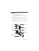
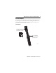
POINT I/O 4 Channel Analog Current Output Module 7 About the Module Note that this series C product can be used with the following: • DeviceNet and PROFIBUS adapters • ControlNet and EtherNet/IP adapters, using RSLogix 5000 software, version 11 or later See the figures to familiarize yourself with major parts of the module, noting that the wiring base assembly is one of the following: • 1734-TB or 1734-TBS POINT I/O two-piece terminal base, which includes the 1734-RTB removable terminal block and 1734-MB m
POINT I/O 4 Channel Analog Current Output Module Module locking mechanism Module wiring diagram DIN rail locking screw (orange) Slide-in writable label Insertable I/O module Handle Mechanical keying (orange) Interlocking side pieces 1734-TOP or 1734-TOPS one-piece terminal base with screw or spring clamp 44221 Install the Mounting Base To install the mounting base on the DIN rail, proceed as follows. 1.
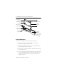
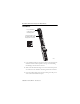
POINT I/O 4 Channel Analog Current Output Module 9 Install the I/O Module The module can be installed before, or after base installation. Make sure that the mounting base is correctly keyed before installing the module into the mounting base. In addition, make sure the mounting base locking screw is positioned horizontal referenced to the base. 1734-TB Base Turn the keyswitch to align the number with the notch. Notch position 3 is shown.
POINT I/O 4 Channel Analog Current Output Module 1734-TOP Base Be sure the DIN-rail locking screw is in the horizontal position. Turn the keyswitch to align the number with the notch. Notch position 1 is shown. 44325 44228 1. Using a bladed screwdriver, rotate the keyswitch on the mounting base clockwise until the number required for the type of module being installed aligns with the notch in the base. 2. Make certain the DIN rail locking screw is in the horizontal position.
POINT I/O 4 Channel Analog Current Output Module 11 Install the Removable Terminal Block (RTB) A removable terminal block is supplied with your wiring base assembly. To remove, pull up on the RTB handle. This allows the mounting base to be removed and replaced as necessary without removing any of the wiring. To reinsert the removable terminal block, proceed as follows. 1. Insert the end opposite the handle into the base unit. This end has a curved section that engages with the wiring base. 2.
POINT I/O 4 Channel Analog Current Output Module Install a 1734-TOPS Base 1. Position the base vertically above the installed units, such as an adapter, power supply, or existing module. 2. Slide the base down, allowing the interlocking side pieces to engage the adjacent installed unit. 3. Press firmly to seat the base on the DIN rail until the base snaps into place. 4. Verify that the DIN-rail locking screw is in a horizontal, locked position before inserting an I/O module.
POINT I/O 4 Channel Analog Current Output Module 13 Default Data Map for the 1734-OE4C Analog Output Module Message size: 4 Bytes 15 Produces (scanner Rx) 14 13 12 11 10 09 08 07 High Byte - Channel 1 Status Not used C F Where: 03 02 01 00 H C A C M C F L C A C M C F 0 2 0 1 0 0 L C A Low Byte - Channel 2 Status C M L C A H C A 04 Not used High Byte - Channel 3 Status Not used 05 Low Byte - Channel 0 Status C M L C A H C A 06 C F Not used H C A CF = Channel Fault st
POINT I/O 4 Channel Analog Current Output Module Wire the Current Output Analog Module 1734 OE4C Output 0 connection 0 Output 1 connection 1 Output 2 connection 2 Output 3 connection 3 C = Common V = Supply C4 5C V6 7V 0 AC or DC Current output device 44352 1 Out 0 Out 1 Out 2 Out 3 2 3 Current ouput device 4-wire 2-wire 4 5 C C 6 Out = Output channel C = Common V = 24V DC 7 V V Chas Gnd Channel Current Output Common Supply 0 0 4 6 1 1 5 7 2 2 3 3 12/24V D
POINT I/O 4 Channel Analog Current Output Module 15 Interpret the Status Indicators Module status Module Status Network status Network Status NODE: 4-20mA Analog Output Status of output 0 0 Status of output 1 Status of output 2 1 Status of output 3 3 2 1734 OE4C 44352 Indicator State Description Module Status Off No power applied to device Green Device operating normally Flashing green Device needs commissioning due to configuration missing, incomplete or incorrect.
POINT I/O 4 Channel Analog Current Output Module Indicator State Description Network Status Off Device is not on-line - Device has not completed dup_MAC_id test - Device not powered - check module status indicator Flashing green Device is on-line but has no connections in the established state. Green Device on-line and has connections in the established state. Flashing red One or more I/O connections in timed-out state Red Critical link failure - failed communication device.
POINT I/O 4 Channel Analog Current Output Module 17 Specifications Output Specifications Attribute Value Number of outputs 4 analog, single-ended, non-isolated Resolution current 16 bits - over 0…21mA 0.32 μA/cnt) Output current terminal 0 mA output until communication established 4…20 mA user configurable 0…20 mA user configurable Absolute accuracy(1) current terminal, min 0.4% (0.
POINT I/O 4 Channel Analog Current Output Module General Specifications Attribute Value Module location 1734-TB or -TBS wiring base assembly POINTBus current, max 75 mA Power dissipation, max 1.86W max @ 750 Ω on each output 2.15W max @ 0 Ω on each output Thermal dissipation, max at 28.8V DC 750 Ω load on each output – 6.34 BTU/hr 0 Ω load on each channel – 7.33 BTU/hr Supply voltage, backplane 5V DC Supply voltage range, field power input 10…28.
POINT I/O 4 Channel Analog Current Output Module 19 General Specifications Attribute Value Weight, approx. 36.9 g (1.3 oz) North American temp code T4A IEC temp code T4 (1) Use this conductor category information for planning conductor routing as described in Industrial Automation Wiring and Grounding Guidelines, publication 1770-4.1.
POINT I/O 4 Channel Analog Current Output Module Environmental Specifications Attribute Value ESD immunity IEC 61000-4-2: 6 kV contact discharges 8 kV air discharges Radiated RF immunity IEC 61000-4-3: 10V/m with 1 kHz sine-wave 80% AM from 80…2000 MHz 10V/m with 200 Hz 50% Pulse 100% AM at 900 MHz 10V/m with 200 Hz 50% Pulse 100% AM at 1890 MHz 3V/m with 1 kHz sine-wave 80% AM from 2000…2700 MHz EFT/B immunity IEC 61000-4-4: ±3 kV at 5 kHz on power ports ±3 kV at 5 kHz on signal ports Surge tran
POINT I/O 4 Channel Analog Current Output Module 21 Certifications Certification (when Value product is marked)(1) c-UL-us UL Listed Industrial Control Equipment, certified for US and Canada. See UL File E65584. UL Listed for Class I, Division 2 Group A,B,C,D Hazardous Locations, certified for U.S. and Canada. See UL File E194810. CE European Union 2004/108/EC EMC Directive, compliant with: EN 61326-1; Meas./Control/Lab.
POINT I/O 4 Channel Analog Current Output Module Additional Resources These documents contain additional information concerning related Rockwell Automation products. Resource Description POINT I/O Digital and Analog Modules and POINTBlock I/O Modules User Manual, publication 1734-UM001. Provides details about how to install, configure, and troubleshoot your module. You can view or download publications at http://www.literature.rockwellautomation.com.
POINT I/O 4 Channel Analog Current Output Module 23 Notes: Publication 1734-IN034B-EN-P - November 2010
Rockwell Automation Support Rockwell Automation provides technical information on the Web to assist you in using its products. At http://support.rockwellautomation.com, you can find technical manuals, a knowledge base of FAQs, technical and application notes, sample code and links to software service packs, and a MySupport feature that you can customize to make the best use of these tools.