Installation Instructions POINT I/O Protected Output Module (Cat. No.
POINT I/O Protected Output Module Important User Information Because of the variety of uses for the products described in this publication, those responsible for the application and use of these products must satisfy themselves that all necessary steps have been taken to assure that each application and use meets all performance and safety requirements, including any applicable laws, regulations, codes and standards.
POINT I/O Protected Output Module IMPORTANT ATTENTION ! 3 Identifies information that is critical for successful application and understanding of the product. Environment and Enclosure This equipment is intended for use in a Pollution Degree 2 industrial environment, in overvoltage Category II applications (as defined in IEC publication 60664-1), at altitudes up to 2000 meters without derating. This equipment is considered Group 1, Class A industrial equipment according to IEC/CISPR Publication 11.
POINT I/O Protected Output Module WARNING ! EXPLOSION HAZARD • Do not disconnect equipment unless power has been removed or the area is known to be nonhazardous. • Do not disconnect connections to this equipment unless power has been removed or the area is known to be nonhazardous. Secure any external connections that mate to this equipment by using screws, sliding latches, threaded connectors, or other means provided with this product.
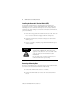
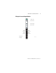
POINT I/O Protected Output Module 5 module into the mounting base. In addition, make sure the mounting base locking screw is positioned horizontal referenced to the base. 1. Using a bladed screwdriver, rotate the keyswitch (2) on the mounting base clockwise until the number required for the type of module being installed aligns with the notch in the base. 2. Make certain the DIN rail locking screw is in the horizontal position. (You cannot insert the module if the locking mechanism is unlocked.) 3.
POINT I/O Protected Output Module Installing the Removable Terminal Block (RTB) A removable terminal block is supplied with your wiring base assembly. To remove, pull up on the RTB handle. This allows the mounting base to be removed and replaced as necessary without removing any of the wiring. To reinsert the removable terminal block, proceed as follows. 1. Insert the end opposite the handle into the base unit. This end has a curved section that engages with the wiring base. 2.
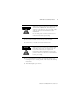
POINT I/O Protected Output Module WARNING ! 7 When you connect or disconnect the Removable Terminal Block (RTB) with field side power applied, an electrical arc can occur. This could cause an explosion in hazardous location installations. Be sure that power is removed or the area is nonhazardous before proceeding. 3. Press on the module lock on the top of the module. 4. Pull on the I/O module to remove from the base.
POINT I/O Protected Output Module Communicating with Your Module I/O messages are sent to (consumed) and received from (produced) the POINT I/O modules. These messages are mapped into the processor’s memory. This POINT I/O output module produces 1 byte of input data (scanner Rx) (status). It consumes 1 byte of I/O data (scanner Tx).
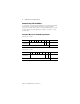
POINT I/O Protected Output Module 9 Wiring the Protected Output Modules Module Status Module Status Network Status Network Status NODE: Protected Sourcing Output Status of Output 0 0 Status of Output 1 1 1734 OB2EP C = Common V = Supply Output 0 Connection Output 1 Connection Output 0 Connection Output 1 Connection C C V V 42016 Publication 1734-IN586A-EN-P - December 2001
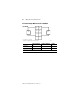
POINT I/O Protected Output Module dc Protected Output Module Cat. No. 1734-OB2EP 1734-OB2EP 1 0 Out 0 Out 1 2 3 Out 0 Out 1 Load Load 4 5 C C V V 6 7 V = 12/24V dc, C = Common Field power is supplied from internal power bus 42014 Output Terminal Common Terminal Power Channel 0 0, 2 4 6 Channel 1 1, 3 5 7 Module power is supplied from the internal power bus.
POINT I/O Protected Output Module 11 Troubleshooting with the Indicators 1734-OB2EP Module Status Module Status Network Status Network Status NODE: Protected Sourcing Output 0 Status of Output 0 1 Status of Output 1 1734 OB2EP Indication Probable Cause Module Status Off No power applied to device Green Device operating normally Flashing Green Device needs commissioning due to configuration missing, incomplete or incorrect. Flashing Red Recoverable fault.
POINT I/O Protected Output Module Indication Probable Cause Network Status Off Device is not on-line - Device has not completed dup_MAC_id test. - Device not powered - check module status indicator Flashing Green Device is on-line but has no connections in the established state. Green Device on-line and has connections in the established state. Flashing Red One or more I/O connections in timed-out state Red Critical link failure - failed communication device.
POINT I/O Protected Output Module 13 Safety Approvals The following information applies when operating this equipment in hazardous locations: Informations sur l’utilisation de cet équipement en environnements dangereux: Products marked “CL I, DIV 2, GP A, B, C, D” are suitable for use in Class I Division 2 Groups A, B, C, D, Hazardous Locations and nonhazardous locations only. Each product is supplied with markings on the rating nameplate indicating the hazardous location temperature code.
POINT I/O Protected Output Module Specifications - 1734-OB2EP Protected Output Module Output Specifications - Meets IEC 1+ 24V dc Output Specifications Number of Outputs 2 (1 group of 2) non-isolated, sourcing ON-State Voltage Range 10V dc minimum 24V dc nominal 28.8V dc maximum ON-State Voltage Drop 0.7V dc maximum (at 30V dc, 55°, full load condition) ON-State Current 1.0mA minimum per channel OFF-State Voltage 28.8V dc maximum OFF-State Leakage 0.
POINT I/O Protected Output Module 15 Environmental Conditions Operational Temperature IEC 60068-2-1 (Test Ad, Operating Cold), IEC 60068-2-2 (Test Bd, Operating Dry Heat), IEC 60068-2-14 (Test Nb, Operating Thermal Shock): -20 to 55°C (-4 to 131°F) Storage Temperature IEC 60068-2-1 (Test Ab, Unpackaged Nonoperating Cold), IEC 60068-2-2 (Test Bc, Unpackaged Nonoperating Dry Heat), IEC 60068-2-14 (Test Na, Unpackaged Nonoperating Thermal Shock): -40 to 85°C (-40 to 185°F) Relative Humidity IEC 60068-2-
Agency Certification (when product is marked) -UL-US - UL Listed Industrial Control Equipment, certified for US and Canada C-UL-US - UL Listed for Class I, Division 2, Groups A, B, C and D Hazardous locations, certified for US and Canada CE3 - European Union 89/336/EEC EMC Directive, C compliant with: EN 50081-2; Industrial Emissions EN 50082-2; Industrial Immunity EN 61326; Meas./Control/Lab.