Installation Instructions POINT I/O 120/220V AC Output Module Catalog numbers 1734-OA2, 1734-OA4, Series C Table of Contents Topic Page Important User Information 2 Environment and Enclosure 3 Preventing Electrostatic Discharge 3 North American Hazardous Location Approval 4 European Hazardous Location Approval 5 Before You Begin 6 Install the Mounting Base 8 Install the Module 9 Install the Removable Terminal Block 11 Remove a Mounting Base 12 Wire the Module 13 Communicate with You
POINT I/O 120/220V AC Output Module Important User Information Solid-state equipment has operational characteristics differing from those of electromechanical equipment. Safety Guidelines for the Application, Installation and Maintenance of Solid State Controls (Publication SGI-1.1 available from your local Rockwell Automation sales office or online at http://www.rockwellautomation.
POINT I/O 120/220V AC Output Module 3 Environment and Enclosure ATTENTION: This equipment is intended for use in a Pollution Degree 2 industrial environment, in overvoltage Category II applications (as defined in IEC publication 60664-1), at altitudes up to 2000 meters (6562 ft) without derating. This equipment is considered Group 1, Class A industrial equipment according to IEC/CISPR Publication 11.
POINT I/O 120/220V AC Output Module North American Hazardous Location Approval The following information applies when operating this equipment in hazardous locations: Informations sur l’utilisation de cet équipement en environnements dangereux: Products marked "CL I, DIV 2, GP A, B, C, D" are suitable for use in Class I Division 2 Groups A, B, C, D, Hazardous Locations and nonhazardous locations only.
POINT I/O 120/220V AC Output Module 5 European Hazardous Location Approval The following applies when the product bears the Ex Marking This equipment is intended for use in potentially explosive atmospheres as defined by European Union Directive 94/9/EC.
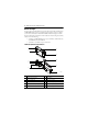
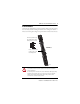
POINT I/O 120/220V AC Output Module Before You Begin You can use these Series C POINT I/O™ 120/220V AC Output modules with DeviceNet and PROFIBUS adapters. If you are using RSLogix 5000 software, version 11 or higher, you can also use the Series C modules with ControlNet and Ethernet adapters. Use this diagram to identify the external features of the module.
POINT I/O 120/220V AC Output Module 7 1 2 9 3 8 4 7 6 5 45712 Description Description 1 Module locking mechanism 6 Interlocking side pieces 2 Slide-in writable label 7 Mechanical keying 3 Insertable I/O module 8 DIN rail locking screw (orange) 4 Removable Terminal Block handle 9 Module wiring diagram 5 1734-TOP or 1734-TOPS one-piece terminal base with screw or spring clamp Publication 1734-IN009E-EN-E - March 2013
POINT I/O 120/220V AC Output Module Install the Mounting Base To install the mounting base on the DIN rail, proceed as follows: ATTENTION: This product is grounded through the DIN rail to chassis ground. Use zinc-plated yellow-chromate steel DIN rail to assure proper grounding. The use of other DIN rail materials (for example, aluminum or plastic) that can corrode, oxidize, or are poor conductors, can result in improper or intermittent grounding.
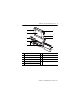
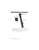
POINT I/O 120/220V AC Output Module 9 Install the Module The module can be installed before or after base installation. Make sure that the mounting base is correctly keyed before installing the module into the mounting base. In addition, make sure the mounting base locking screw is positioned horizontal referenced to the base. Turn the keyswitch to align the number with the notch. Notch position 3 is shown. 1734-TB Base Make sure the DIN rail locking screw is in the horizontal position.
POINT I/O 120/220V AC Output Module Make sure the DIN-rail locking screw is in the horizontal position. Turn the keyswitch to align the number with the notch. Notch position 1 is shown. 1734-TOP Base 45697 1. Using a bladed screwdriver, rotate the keyswitch on the mounting base clockwise until the number required for the type of module being installed aligns with the notch in the base. 2. Make certain the DIN rail locking screw is in the horizontal position.
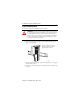
POINT I/O 120/220V AC Output Module 11 Install the Removable Terminal Block A Removable Terminal Block (RTB) is supplied with your wiring base assembly. To remove, pull up on the RTB handle. This allows the mounting base to be removed and replaced as necessary without removing any of the wiring. To reinsert the Removable Terminal Block, proceed as follows: 1. Insert the end opposite the handle into the base unit. This end has a curved section that engages with the wiring base. 2.
POINT I/O 120/220V AC Output Module Remove a Mounting Base To remove a mounting base, you must remove any installed module and the module installed in the base to the right. Remove the Removable Terminal Block, if wired. 1. Unlatch the RTB handle on the I/O module. 2. Pull on the RTB handle to remove the Removable Terminal Block. 3. Press on the module lock on the top of the module. 4. Pull on the I/O module to remove from the base. 5. Repeat steps 1, 2, 3 and 4 for the module to the right. 6.
POINT I/O 120/220V AC Output Module 13 Wire the Module 1734-OA2 1734-OA4 Module status Network status Module Status Module status Network status Network Status NODE: NODE: 0 Status of output 1 1 120/220VAC Output Status of output 0 Status of output 1 Status of output 2 Status of output 3 1734 OA2 Channel 0 connection No connection L2/N L1 Network Status NODE: 120/220VAC Output Status of output 0 Module Status 0 1 2 3 1734 OA4 Channel 1 connection Channel 0 connection Channel 1 connecti
POINT I/O 120/220V AC Output Module Wiring for 1734-OA2 0 1 Ch 0 Ch 1 NC NC L2/N L2/N 2 L1 = 120/220V AC supply L2/N = 120/220V AC return Ch 0 = Channel 0 Ch 1 = Channel 1 Field power is supplied from internal power bus 3 Load 4 Load 5 6 7 L1 L1 Channel Output Terminal Common Terminal Power 0 0 4 6 1 1 5 7 Module power is supplied from the internal power bus.
POINT I/O 120/220V AC Output Module 15 Communicate with Your Module POINT I/O modules send (consume) and receive (produce) messages. These messages are mapped onto the processor’s memory. This POINT I/O output module consumes 1 Byte of output data (scanner Tx). It does not produce data (scanner Rx). Refer to the following default data map tables.
POINT I/O 120/220V AC Output Module Interpret Status Indicators Refer to the following diagram and table for information on how to interpret the status indicators.
POINT I/O 120/220V AC Output Module 17 Indicator Status for Modules Module status Status Description Recommended Action Off No power applied to device. Apply power to device. Green Device operating normally. None. Flashing green Device needs commissioning due to missing, incomplete, or incorrect configuration. Configure device properly. Flashing red Recoverable fault. 1. Cycle power to device. 2. If condition persists, replace device.
POINT I/O 120/220V AC Output Module Specifications POINT I/O 120/220V AC Output Module – 1734-OA2, 1734-OA4, Series C Attribute Value Outputs per module 1734-OA2 – 2 nonisolated, sourcing 1734-OA4 – 4 nonisolated, sourcing On-state voltage range, min 74V AC On-state voltage range, nom 120/220V AC On-state voltage range, max 264V AC On-state voltage drop, max 1.0V @ 0.75 A On-state current, min 10 mA per channel On-state current, max 750 mA per channel For 1734-OA4, 750 mA per output, 2.
POINT I/O 120/220V AC Output Module 19 General Specifications Attribute Value Thermal dissipation, max 1734-OA2 – 6.8 BTU @ @ 264V AC 1734-OA4 – 11.9 BTU @ @ 264V AC Isolation voltage 240V (continuous), Reinforced Insulation Type tested @ 3250V DC for 60 s, field-side to system External AC power supply voltage, nom 120/220V DC @ 60 Hz External AC power supply voltage range 85...264V DC @ 27...63 Hz Dimensions, approx., HxWxD 56.0 x 12.0 x 75.5 mm (2.21 x 0.47 x 2.97 in.
POINT I/O 120/220V AC Output Module Environmental Specifications Attribute Value Vibration IEC 60068-2-6 (Test Fc, Operating): 5 g @ 10...500 Hz Shock, operating IEC 60068-2-27 (Test Ea, Unpackaged Shock): 30 g Shock, nonoperating IEC 60068-2-27 (Test Ea, Unpackaged Shock): 50 g Emissions CISPR 11: Group 1, Class A ESD immunity IEC 61000-4-2: 6 kV contact discharges 8 kV air discharges Radiated RF immunity IEC 61000-4-3: 10V/m with 1 kHz sine-wave 80% AM from 80...
POINT I/O 120/220V AC Output Module 21 Certifications Certification (when product is marked)(1) Value C-Tick Australian Radiocommunications Act, compliant with: AS/NZS CISPR 11; Industrial Emissions Ex European Union 94/9/EC ATEX Directive, compliant with: EN 60079-15; Potentially Explosive Atmospheres, Protection "n" EN 60079-0; General Requirements II 3 G Ex nA IIC T4 Gc DEMKO 04 ATEX 0330347X When used at or below 120V AC KC Korean Registration of Broadcasting and Communications Equipment, compl
POINT I/O 120/220V AC Output Module Notes: Publication 1734-IN009E-EN-E - March 2013
POINT I/O 120/220V AC Output Module 23 Notes: Publication 1734-IN009E-EN-E - March 2013
Rockwell Automation Support Rockwell Automation provides technical information on the Web to assist you in using its products. At http://www.rockwellautomation.com/support/, you can find technical manuals, a knowledge base of FAQs, technical and application notes, sample code and links to software service packs, and a MySupport feature that you can customize to make the best use of these tools.