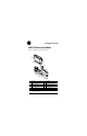
Installation Instructions POINT I/O Source Input Module 9 1 0 N S e N ta tw O tu o D s rk E: M St od at u us le Cat. No.
POINT I/O Source Input Module This Series C product can be used with DeviceNet and PROFIBUS adapters. It can be used with ControlNet and Ethernet adapters using RSLogix 5000, version 11 (or higher) software. Important User Information Solid state equipment has operational characteristics differing from those of electromechanical equipment. Safety Guidelines for the Application, Installation and Maintenance of Solid State Controls (Publication SGI-1.
POINT I/O Source Input Module 3 Important User Information WARNING ATTENTION Identifies information about practices or circumstances that can cause an explosion in a hazardous environment, which may lead to personal injury or death, property damage, or economic loss. Identifies information about practices or circumstances that can lead to personal injury or death, property damage, or economic loss.
POINT I/O Source Input Module ATTENTION Environment and Enclosure This equipment is intended for use in a Pollution Degree 2 industrial environment, in overvoltage Category II applications (as defined in IEC publication 60664-1), at altitudes up to 2000 meters without derating. This equipment is considered Group 1, Class A industrial equipment according to IEC/CISPR Publication 11.
POINT I/O Source Input Module WARNING ATTENTION 5 EXPLOSION HAZARD • Do not disconnect equipment unless power has been removed or the area is known to be nonhazardous. • Do not disconnect connections to this equipment unless power has been removed or the area is known to be nonhazardous. Secure any external connections that mate to this equipment by using screws, sliding latches, threaded connectors, or other means provided with this product.
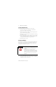
POINT I/O Source Input Module Installing the Mounting Base To install the mounting base on the DIN rail, proceed as follows. 1. Position the mounting base vertically above the installed units (adapter, power supply or existing module). 2. Slide the mounting base down allowing the interlocking side pieces to engage the adjacent module or adapter. 3. Press firmly to seat the mounting base on the DIN rail. The mounting base will snap into place. 4.
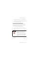
POINT I/O Source Input Module 7 2. Make certain the DIN rail locking screw is in the horizontal position. You cannot insert the module if the locking mechanism is unlocked. 3. Insert the module straight down into the mounting base and press to secure. The module will lock into place. Installing the Removable Terminal Block (RTB) A removable terminal block is supplied with your wiring base assembly. To remove, pull up on the RTB handle.
POINT I/O Source Input Module Removing a Mounting Base To remove a mounting base, you must remove any installed module, and the module installed in the base to the right. Remove the removable terminal block (if wired). 1. Unlatch the RTB handle on the I/O module. 2. Pull on the RTB handle to remove the removable terminal block. WARNING When you connect or disconnect the Removable Terminal Block (RTB) with field side power applied, an electrical arc can occur.
POINT I/O Source Input Module 9 Communicating with Your Module I/O messages are sent to (consumed) and received from (produced) the POINT I/O modules. These messages are mapped into the processor’s memory. This POINT I/O input module produces 1 byte of input data (scanner Rx). It does not consume I/O data (scanner Tx).
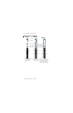
POINT I/O Source Input Module Wiring the Source Input Modules 1734-IV2 1734-IV4 Module Status Module Status Network Status Network Status 24VDC Source Input Module Status Network Status NODE: Status of Input 1 1 24VDC Source Input 24VDC Source Input Status of Input 0 0 Status of Input 2 Status of Input 3 1734 IV2 NC Module Status Network Status NODE: NODE: Input 0 1734-IV8 0 Status of Input 0 and 4 0 4 1 Status of Input 1 and 5 1 5 2 Status of Input 2 and 6 2 6 3 Status o
POINT I/O Source Input Module 11 Wiring for 1734-IV2 When you connect or disconnect wiring while field side power is on, an electrical arc can occur. This could cause an explosion in hazardous location installations. WARNING Be sure that power is removed or the area is nonhazardous before proceeding.
POINT I/O Source Input Module Wiring for 1734-IV4 When you connect or disconnect wiring while field side power is on, an electrical arc can occur. This could cause an explosion in hazardous location installations. WARNING Be sure that power is removed or the area is nonhazardous before proceeding.
POINT I/O Source Input Module 13 Wiring for 1794-IV8 When you connect or disconnect wiring while field side power is on, an electrical arc can occur. This could cause an explosion in hazardous location installations. WARNING Be sure that power is removed or the area is nonhazardous before proceeding.
POINT I/O Source Input Module Example of Wiring for 1734-IV8 Using 2-Wire Proximity Switches When you connect or disconnect wiring while field side power is on, an electrical arc can occur. This could cause an explosion in hazardous location installations. WARNING Be sure that power is removed or the area is nonhazardous before proceeding.
POINT I/O Source Input Module 15 Example of Wiring for 1734-IV8 Using 3-Wire Proximity Switches When you connect or disconnect wiring while field side power is on, an electrical arc can occur. This could cause an explosion in hazardous location installations. WARNING Be sure that power is removed or the area is nonhazardous before proceeding.
POINT I/O Source Input Module Troubleshooting with the Indicators 1734-IV2 Module Status Network Status NODE: 1734-IV4 Module Status Module Status Module Status Network Status 0 Status of Input 0 1 Status of Input 1 Status of Input 2 Status of Input 3 Indication Module Status Network Status Network Status Network Status NODE: NODE: 24VDC Source Input 1734 IV2 1734-IV8 24VDC Source Input 24VDC Source Input 0 Status of Input 0 and 4 0 4 1 Status of Input 1 and 5 1 5 2 Status o
POINT I/O Source Input Module Indication 17 Probable Cause Network Status Off Device is not on-line - Device has not completed dup_MAC_id test. - Device not powered - check module status indicator Flashing Green Device is on-line but has no connections in the established state. Green Device on-line and has connections in the established state. Flashing Red One or more I/O connections in timed-out state Red Critical link failure - failed communication device.
POINT I/O Source Input Module North American Hazardous Location Approval The following information applies when operating this equipment in hazardous locations: Informations sur l’utilisation de cet équipement en environnements dangereux: Products marked “CL I, DIV 2, GP A, B, C, D” are suitable for use in Class I Division 2 Groups A, B, C, D, Hazardous Locations and nonhazardous locations only.
POINT I/O Source Input Module 19 European Hazardous Location Approval European Zone 2 Certification (The following applies when the product bears the EEx Marking) This equipment is intended for use in potentially explosive atmospheres as defined by European Union Directive 94/9/EC.
POINT I/O Source Input Module Specifications - 1734-IV2, -IV4 and -IV8 Source Input Modules Input Specifications (IEC 3 24V dc Input Compliant) Inputs per Module 1734-IV2 - 2 (1 group of 2), sourcing 1734-IV4 - 4 (1 group of 4), sourcing 1734-IV8 - 8 (1 groups of 8) sourcing ON-State Voltage 10V dc minimum 24V dc nominal 28.8V dc maximum ON-State Current 2mA minimum 4mA nominal @ 24V dc 5mA maximum OFF-State Voltage 5V dc maximum OFF-State Current 1.5mA minimum Input Impedance 4.
POINT I/O Source Input Module 21 Environmental Conditions Operational Temperature IEC 60068-2-1 (Test Ad, Operating Cold), IEC 60068-2-2 (Test Bd, Operating Dry Heat), IEC 60068-2-14 (Test Nb, Operating Thermal Shock): -20 to 55°C (-4 to 131°F) Storage Temperature IEC 60068-2-1 (Test Ab, Unpackaged Nonoperating Cold), IEC 60068-2-2 (Test Bb, Unpackaged Nonoperating Dry Heat), IEC 60068-2-14 (Test Na, Unpackaged Nonoperating Thermal Shock): -40 to 85°C (-40 to 185°F) Relative Humidity IEC 60068-2-30 (Te
POINT I/O Source Input Module Field Wiring Terminations Mass 1734-IV2 0 - Input 0 2 - No Connection 4 - Common 6 - User Supply 1734-IV4 0 - Input 0 2 - Input 2 4 - Common 6 - User Supply 1734-IV8 0 - Input 0 2 - Input 2 4 - Input 4 6 - Input 6 1 - Input 1 3 - No Connection 5 - Common 7 - User Supply 1 - Input 1 3 - Input 3 5 - Common 7 - User Supply 1 - Input 1 3 - Input 3 5 - Input 5 7 - Input 7 1734-IV2 - 1.10 oz/31.2 grams 1734-IV4 - 1.12 oz/31.8 grams 1734-IV8 - 1.14 oz/32.
POINT I/O Source Input Module 23 Publication 1734-IN052D-EN-E - February 2005
POINT I/O is a trademark of Rockwell Automation# DeviceNet is a trademark of ODVA, Inc. Publication 1734-IN052D-EN-E - February 2005 Supersedes Publication 1734-IN052C-EN-P - April 2002 PN 957928-23 Copyright © 2005 Rockwell Automation. All rights reserved.