
User Manual Owner's manual

Publication 1734-UM004F-EN-E - December 2012
16 Install the Module
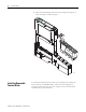
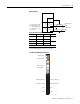
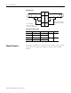
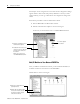
Wiring Diagram
Chapter Summary
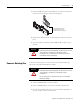
This chapter explained how to install and wire the modules. The next chapter
describes how to configure your POINT I/O Thermocouple and RTD
Modules.
Input Channel Power Limits
Channel High Signal (+) Low Signal (-) Return Shield
In 0/A 0 4 6
In 0/B 2
In 1.A 1 5 7
In 1/B 3
In 0/A In 1/A
In 1/BIn 0/B
RET 0 RET 1
ShieldShield
3-wire
RTD
In = Input channel
RET = Sensor return
Shield = Sensor cable shield
3
5
0
1
2
4
2-wire
RTD
6
7
When using 2-wire RTDs,
Insert 1 Ω resistor IN/B to
RET.
1 Ω
resistor