POINT I/O Thermocouple and RTD Modules Catalog Numbers 1734-IR2, 1734-IR2E and 1734-IT2I User Manual
Important User Information Solid state equipment has operational characteristics differing from those of electromechanical equipment. Safety Guidelines for the Application, Installation and Maintenance of Solid State Controls (publication SGI-1.1 available from your local Rockwell Automation sales office or online at http://literature.rockwellautomation.com) describes some important differences between solid state equipment and hard-wired electromechanical devices.
Table of Contents Summary of Changes Important User Information . . . . . . . . . . . . . . . . . . . . . . . . . . . . . . . . . . 2 New and Revised Information . . . . . . . . . . . . . . . . . . . . . . . . . . . . . 7 Change Bars . . . . . . . . . . . . . . . . . . . . . . . . . . . . . . . . . . . . . . . . . . . . 7 Preface Who Should Use this Manual . . . . . . . . . . . . . . . . . . . . . . . . . . . . . . . . . 9 Purpose of this Manual . . . . . . . . . . . . . . . . . . . . . . . . . . . . . .
iv Table of Contents Using the RSNetWorx Commissioning Tool. . . . . . . . . . . . . . . . . Use Sequential Auto Addressing. . . . . . . . . . . . . . . . . . . . . . . . . . . Use Third Party Configuration Software . . . . . . . . . . . . . . . . . . . . Add the Adapter to Your Network. . . . . . . . . . . . . . . . . . . . . . . . . . . . Add I/O Modules to Your Network POINTBus . . . . . . . . . . . . .
Table of Contents v Understanding Data, Connection, and Communication Formats . . . . . . . . . . . . . . . . . . . . . . . . . . . . . . . . . . . . 63 Configure Your Module. . . . . . . . . . . . . . . . . . . . . . . . . . . . . . . . . . . . . 64 Use the Help Button . . . . . . . . . . . . . . . . . . . . . . . . . . . . . . . . . . . . . . . 65 Working with Dialogs . . . . . . . . . . . . . . . . . . . . . . . . . . . . . . . . . . . . . . 65 Work with Dialogs for RTD Modules . . . . . . . . . . . .
vi Table of Contents Notes: Publication 1734-UM004F-EN-E - December 2012
Summary of Changes This publication contains new and revised information not in the last release. New and Revised Information See the table for a summary of the major changes in this manual. Revised to include Chapter New Appendix on Absolute Accuracy and Accuracy Drift calculation Appendix B Change Bars Change bars (as shown with this paragraph) show the areas in this manual that differ from previous editions and indicate the addition of new or revised information.
viii Summary of Changes Notes: Publication 1734-UM004F-EN-E - December 2012
Preface Read this preface to familiarize yourself with the rest of the manual. It provides information concerning: • • • • Who Should Use this Manual who should use this manual the purpose of this manual related documentation conventions used in this manual You must be able to use your selected configuration software to set up and calibrate these modules. You must have the capability to download and use files. We assume you know how to do this in this manual.
x Resource Description Analog Output Modules Installation Instructions, publication 1734-IN002 Information about how to install 1734-OE2C and 1734-OE2V, Series C Point I/O Current and Voltage Output Analog Modules. Cold Junction Wiring Base Assembly Installation Instruction, publication 1734-IN583 Information about how to install the POINT I/O Cold Junction Compensation Wiring Base Assembly.
Chapter 1 About POINT I/O Modules Overview Module Features Read this chapter to familiarize yourself with configurable features on the 1734-IT2I, 1734-IR2, and 1734-IR2E modules. The following table lists where to find specific information in this chapter.
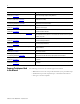
2 About POINT I/O Modules Selecting a Module Input Type The 1734-IT2I module consists of two isolated millivolt inputs (+70 mV). Configure the module to do the linearization necessary for thermocouple inputs. See the table for a list of supported thermocouple input types. Supported Sensor Types – Thermocouple mV (default) -70...+70 mV B 572...3272 °F (300...1800 °C) C 32...4199 °F (0...2315 °C) E -418...+1832 °F (-250...+1000 °C) J -346...+2192 °F (-210...+1200 °C) K -418...+2502 °F (-250..
About POINT I/O Modules 3 Default Data Map for the Thermocouple Input Module (catalog number 1734-IT2I) 15 Produces (scanner Rx) 14 13 12 11 10 09 08 07 06 05 04 Input Channel 0 - High Byte Input Channel 0 - Low Byte Input Channel 1 - High Byte Input Channel 1 - Low Byte Status Byte for Channel 1 Status Byte for Channel 0 HA LA CM CF OR UR HHA LLA 03 02 01 00 HA LA CM CF 03 02 01 00 HA LA CM CF OR UR HHA LLA OR UR Cold Junction Temperature (Selectable: Channel
4 About POINT I/O Modules Data Format (1734-IT2I, 1734-IR2, and 1734-IR2E modules) You must choose a module data format in your user program. Select the format. These are four predefined scales and one custom scale. Data Formats mV Custom Scale ⋅ C Celsius ⋅ F Fahrenheit ⋅ K Kelvin ⋅ R Rankine Predefined Scale °C, F, °R, and °K returns data in tenths of a degree (250 implies 25.0 °). For the 1734-IR2E, ⋅ C, ⋅ F, ⋅ R, and ⋅ K returns data in hundreths of a degree (250 implies 2.50 ⋅ ).
About POINT I/O Modules 5 1734-IR2E RTD Input Module Use Module Alarms RTD Type Low Scaling Endpoint High Scaling Endpoint O hms 100 Ω 200 Ω 100 Ω Ptα = 0.00385 Euro 32 °F (0 °C) 572 °F (300 °C) POINT I/O modules are capable of generating the following alarms.
6 About POINT I/O Modules • Low-Low • High • High-High When the channel input goes below a low alarm or above a high alarm, a bit is set in the data table. All Alarm Status bits can be read individually or by reading the Channel Status Byte (Bits 2...5 for channel 0; bits 10...13 for channel 1). You can configure each channel alarm individually. Open-wire Alarm (1734-IT2I, 1734-IR2, and 1734-IR2E modules) The module has the ability to check for a broken or detached wire.
Chapter 2 Install the Module Overview Read this chapter for information about how to install and wire RTD and thermocouple modules. The following table lists where to find specific information in this chapter.
8 Install the Module Environment and Enclosure ATTENTION This equipment is intended for use in a Pollution Degree 2 industrial environment, in overvoltage Category II applications (as defined in IEC publication 60664-1), at altitudes up to 2000 m (6562 ft) without derating. This equipment is considered Group 1, Class A industrial equipment according to IEC/CISPR Publication 11.
Install the Module ATTENTION 9 POINT I/O is grounded through the DIN rail to chassis ground. Use zinc-plated, yellow-chromated steel DIN rail to assure proper grounding. The use of DIN rail materials (such as aluminum and plastic) that can corrode, oxidize, or are poor conductors can result in improper or intermittent grounding. Secure DIN rail to mounting surface approximately every 200 mm (7.8 in.). You can install the assembly, or just the mounting base.
10 Install the Module 3. Press firmly to seat the mounting base on the DIN rail. The mounting base snaps into place. M Staodule tus Net Sta wo NO tusrk DE: 0 24 So VDC Ouurce tpu t 1 2 3 17 OB34 4E 46003 4. Repeat this procedure for the next mounting base assembly. Install an I/O Module Install the module before or after base installation. Make sure you correctly keyed the mounting base before installing the module into the mounting base.
Install the Module 11 1734-RTD - Position 6 1734-IT2I - Position 6 4 5 6 7 2 3 Turn the keyswitch to align the number with the notch. Notch (position 6 shown) 8 1 2. Make certain the DIN rail locking screw is in the horizontal position, noting that you cannot insert the module if the locking mechanism is unlocked. Make sure the DIN rail locking screw is in the horizontal position.
12 Install the Module 1 O 73 B 4 4E 3 2 1 0 2 S 4V O ou DC ut rc pu e t : M St o d at u us le N S e N ta tw O tu o D s rk E 3. Insert the module straight down into the mounting base and press to secure, locking the module into place. 44012 Install the Removable Terminal Block Publication 1734-UM004F-EN-E - December 2012 A removable terminal block comes with your mounting base assembly.
Install the Module 13 1. Insert the RTB end opposite the handle into the base unit, which has a curved section that engages with the mounting base. Hook the RTB end into the mounting base end, and rotate until it locks into place. 2. Rotate the terminal block into the mounting base until it locks itself in place. 3. If an I/O module is installed, snap the RTB handle into place on the module.
14 Install the Module 4. Remove the module to the right of the base you are removing, noting that the interlocking portion of the base sits under the adjacent module. 5. Use a small-bladed screwdriver to rotate the orange DIN rail locking screw on the mounting base to a vertical position. releasing the locking mechanism. 6. Lift the mounting base straight up to remove. Wire the Modules To wire the thermocouple input modules, refer to the figures.
Install the Module 15 Wiring Diagram 3 Shield 4 0+ = Input channel 0 High 0- = Input channel 0 Low 1+ = Input channel 1 High 1- = Input channel 1 Low Shld = Shield 0- 0+ 6 1+ 5 Thermocouple 0 7 Thermocouple 1 1- Input Channel Power Limits Channel Input High Input Low Shield 0+ 4 01+ 1- 3 5 6 3 7 Power is provided by the internal power bus. To wire RTD modules, refer to the figures.
16 Install the Module Wiring Diagram 0 1 In 0/A In 1/A 2 In 0/B 3-wire RTD 3 In 1/B RET 0 In = Input channel RET = Sensor return Shield = Sensor cable shield 2-wire RTD RET 1 When using 2-wire RTDs, Insert 1 Ω resistor IN/B to RET. 7 6 Shield 1Ω resistor 5 4 Shield Input Channel Power Limits Channel High Signal (+) Low Signal (-) Return Shield In 0/A 0 4 6 5 7 In 0/B In 1.
Chapter 3 Configure Your Module Overview Configuration Overview This chapter describes how to configure your thermocouple input module with RSNetWorx.
18 Configure Your Module Using the RSNetWorx Commissioning Tool Use the RSNetWorx commissioning tool to commission devices (set the node address and the data rate parameters) that are: • connected to a DeviceNet network. • connected via a point-to-point connection. The node commissioning tool works through RSLinx; RSNetWorx does not have to be online when performing the operation. Before you can add any device to a DeviceNet network, it must be commissioned.
Configure Your Module 19 Use Sequential Auto Addressing Sequential Auto Addressing (SAA) reassigns the node address of every module to the right of the one you select. Each module changes its node address to one greater than its neighbor. IMPORTANT Make sure the node address of the selected module is the desired value before issuing the SAA command. When this command is set, each module to the right gets a new address one greater than its neighbor.
20 Configure Your Module This chapter shows configuration in the online mode. Configuration dialogs appear similar in both modes. The primary difference is that if you make changes offline, you must go online before the configuration changes take effect. Perform this procedure to add a communication device. 1. Start the RSNetWorx for DeviceNet software. 2. Add the communication adapter as shown in the figure. In this case, the chosen device was a 1770-KFD RS232 Interface.
Configure Your Module 21 The out-of-the-box node setting for 1734 modules is 63. You can change the setting by using the node commissioning tool. The node commissioning tool is available either online or offline. 1 2 1. Go to the Tools pull-down menu. 2. Select Node Commissioning. 3. Click Browse. 3 4. Select the module to change. 5. The node commissioning dialog returns. It displays the node number and data rate. 6.
22 Configure Your Module Set the Thermocouple Input Module Parameters Using RSNetWorx After adding the module to the network, you must configure the modules for use. IMPORTANT This chapter shows configuration in the online mode. Changes set in this mode take effect when you download to the individual module. Configure the modules as shown in the figure. 1. Right-click the module. You can also left-click the module or name. 2. Click Properties to configure. You see a dialog with a series of tabs.
Configure Your Module 23 Setting Parameters The module name appears here. Type a description here. The module address appears here. (This field is read-only.) This dialog also shows the module’s device identity. These fields are read-only. Click the Device parameters tab to get to the dialog for setting the parameters. At any point, you can click here to finish changing configuration parameters.
24 Configure Your Module Configure Your Thermocouple Input Module Configuration can be divided into two categories: Basic Set-up Parameters and Advanced Setup Parameters. Basic Set-up Parameters The basic parameters you need to set for the thermocouple module consist of: • Temperature units - Select how the input is linearized: – mV/Custom Scale (default) – Celsius – Fahrenheit – Kelvin – Rankine • Thermocouple type - Choose the type of sensor for this input.
Configure Your Module 25 Advanced Setup Parameters Advanced parameters you can set for the thermocouple module consist of: • Notch filter - Select the Notch Filter for the analog to digital converter. At higher frequencies, faster sample rates are possible – 50 Hz – 60 Hz (default) – 100 Hz – 120 Hz – 200 Hz – 240 Hz – 300 Hz – 400 Hz – 480 Hz If the filter value is changed, the module may require calibration to meet specifications. • Digital filter - A digital filter is available on this module.
26 Configure Your Module • Level alarms - low-low, low, high, and high-high - any value from -32,768...+32,767 can be entered. • Scaling - Values returned when input is at low scale value or high scale value.
Configure Your Module 27 Basic Setup 1. Select the temperature scale. 2. Then select the type of thermocouple: B C E J K N R S T or mV 3. Select cold junction compensation if desired. 4. Select how the cold junction data is returned in the produced I/O message. Select None, channel 0, channel 1, or the average of both channels. 5. Download to the device.
28 Configure Your Module Advanced Setup 6. Select the notch filter desired (60 Hz to 480 Hz). 7. Select the digital filter (select as necessary) 8. Enable or disable the latching alarms. 9. Enable or disable the alarms. 10. Apply and download to the device.
Configure Your Module Set the RTD Input Module Parameters Using RSNetWorx 29 After adding the module to the network, you must configure the modules for use. IMPORTANT This chapter shows configuration in the online mode. Changes set in this mode take effect when you download to the individual module. Configure the modules as shown. 1. Right-click the module. You can also left click the module or name. 2. Click Properties to configure. You see a dialog with a series of tabs.
30 Configure Your Module Setting Parameters Click the Device parameters tab to get to the dialog for setting the parameters. The module name appears here. Type a description here. The module address appears here. (This field is read-only.) This dialog also shows the module’s device identity. These fields are read-only. At any point, click here to finish changing configuration parameters. If configuration changes are made in offlin mode, they do not take effect until the system goes online.
Configure Your Module Configure Your RTD Input Module 31 Configuration is divided into basic and advanced parameters. Basic Setup Parameters The basic parameters you need to set for the RTD module consist of: • Temperature units – Use the Temperature Scale parameter to select a predefined scale or a custom scale. Custom Scale allows you to enter the scaling endpoint values. If using Ohms RTD Type, ignore this parameter. Predefined Scales include: Celsius(C), Fahrenheit(F), Kelvin(K), and Rankine(R).
32 Configure Your Module Advanced Setup Parameters Advanced parameters you can set for the RTD module consist of: • Notch filter – Select the Notch Filter for the analog to digital converter. At higher frequencies, faster sample rates are possible – 50 Hz – 60 Hz (default) – 100 Hz – 120 Hz – 200 Hz – 240 Hz – 300 Hz – 400 Hz – 480 Hz If the filter value is changed, the module may require calibration to meet specifications. • Digital filter – A digital filter is available on this module.
Configure Your Module 33 • Scaling – Values returned when input is at low scale value or high scale value. The low and high scale points are different for each sensor input: RTD Module Scaling Limits RTD Type Low Scaling High Scaling Endpoint Endpoint O hms 100 Ω 500 Ω 100 Ω Pt α = 0.00385 Euro 32 °F (0 °C) 932 °F (500 °C) 200 Ω Pt α = 0.00385 Euro 32 °F (0 °C) 932 °F (500 °C) 100 Ω Pt α = 0.003916 U.S. 32 °F (0 °C) 932 °F (500 °C) 200 Ω Pt α = 0.003916 U.S.
34 Configure Your Module Basic Setup 1. Select the type of RTD you are using for channel 0. Repeat for channel 1. 2. Then select the scale for channel 0. Repeat for channel 1. This is the error of Copper RTD (10 Ω Cu427) in O hms. Enter value between -250 and 250 in hundredths of Ohms (such as 361 = 3.61 Ω). If you are using a copper RTD, this value is added to the input reading before linearization.
Configure Your Module 35 Advanced Setup 3. Select the digital filter desired. (Range is 0...10.000 ms.) 4. Enable or disable the latching alarms. 5. Enable or disable the alarms. 6. Select the notch filter. 7. Apply and download to the device.
36 Configure Your Module View the I/O defaults setup and the EDS file by clicking the appropriate tab. Check I/O Status and View the EDS File 1734-IT2I module 1. Click the I/O Defaults tab to display the default characteristics for this module. This dialog shows the input/output defaults for the four modes: Strobe Polled Change of state and Cyclic 2. Click the EDS File tab to display the statistics of the EDS file used to configure this module. 3. Click View File to view the actual EDS file (shown).
Configure Your Module 37 1734-IR2 and 1734-IR2E modules 1. Click the I/O Defaults tab to display the default characteristics for this module. 2. Click the EDS File tab to display the statistics of the EDS file used to configure this module. This dialog shows the input/output defaults for the four modes: Strobe Polled Change of state and Cyclic 3. Click View File to view the actual EDS file (shown). Chapter Summary This chapter explained how to configure the modules.
38 Configure Your Module Publication 1734-UM004F-EN-E - December 2012
Chapter 4 Calibrate Your Module Overview When and How to Calibrate Your Module Use this chapter to calibrate the thermocouple/mV module or the RTD input module. Refer to the table for a summary of what is covered.
40 Calibrate Your Module Calibrate the Thermocouple Input Module To calibrate your thermocouple input module, connect the module in a DeviceNet system similar to that shown in the figure. Apply power to the power supply and module for at least 10 minutes before calibrating the module. IMPORTANT Delete all I/O connections by removing the module from its master's scan list and inhibiting the module in RSLogix. When there is no connection present the Network Status Indicator should flash green.
Calibrate Your Module 41 Access Calibration Parameters in RSNetWorx 1. Double-click the icon of the module to be calibrated to bring up the General Parameter dialog. 2. Click Device parameters. Click Device Parameters to view the parameters. ATTENTION The dialog box layout varies depending on the version of RSNetWorx software you are using. The EDS editor may ask you if you want to upload the configuration from the device. 3.
42 Calibrate Your Module 4. From the Device Parameters dialog, select Calibration at the Groups pull-down. This is the Groups pull-down. Input (mV) Calibration Before calibrating the module you need to select the sensor type and download it to the module. Perform the following procedure from the Device Parameters dialog. IMPORTANT Apply power to the power supply and module for at least 10 minutes before calibrating the module.
Calibrate Your Module 43 1. From the Configuration tab, set the Thermocouple Type to mV (no linearization) for the channel(s) to be calibrated and download to the module. 2. Open the Device Parameter tab and click Calibration Channel Select to bring up your channel selections. For input calibration, choose: Input Channel 0, Input Channel 1, or Both Channels. 3. Select a channel (0 or 1), or select Both Channels. 4. Click Download to Device.
44 Calibrate Your Module 5. Click Calibration Command, and select Begin Calibration. 6. Click the Download to Device button. The status indicator of a channel in calibration mode flashes green. The status indicator of a channel not in calibration turns off. 7. Apply 0.00 mV to the input, referring to the wiring diagram in this section. IMPORTANT Calibration in millivolts allows the sensor calibration to be independent of CJC.
Calibrate Your Module 45 10. Set the source to 70 mV. Module terminal voltage must be exact. 11. Click Accept High Input. 12. Click the Download to Device button. Input calibration is now complete. The status indicator should be solid green (normal) or blinking red (no load). The channel can now be configured to the type of input desired for normal operation.
46 Calibrate Your Module 2. Click Calibration Command and select Begin CJC Calibration. Click calibration command and select Begin CJC calibration. Then download to the module. 3. Click the Download to Device button. 4. Using a 1734-RTB removable terminal block, apply 1000 Ω to the selected CJC channel, referring to the wiring diagram in this section. 5. Select Accept Low CJC and download to the device. 6. Using a 1734-RTB removable terminal block, apply 3000 Ω to the selected CJC channel.
Calibrate Your Module 47 7. Select Accept High CJC and download to the device. 8. If RSNetWorx reports a communication error, or if an error occurred during this calibration, abort calibration and try again. Calibration is done as soon as High and Low calibration for the selected channels is done successfully. When the calibration is accepted by the module, it sets the Bad Cal Status bit for the channel to Good Calibration, as shown here.
48 Calibrate Your Module Tools and Equipment Required to Calibrate Your RTD Module Calibrate the RTD Input Module To calibrate your RTD module, you need the following tools and equipment. Tool or Equipment Description Precision Resistors High precision resistors: 100 Ω, 0.04%, 5 ppm/ oC 500 Ω, 0.03%, 5 ppm/ oC - for 1734-IR2 module 200 Ω, 0.03%, 5 ppm/ oC - for 1734-IR2E module or Calibrated resistor Decade Box, 0.
Calibrate Your Module 49 2. Click Device Parameters to view the parameters. Click Device Parameters to view the parameters. The EDS editor may ask you if you want to upload the configuration from the device. 3. From the EDS editor, if it asks you about uploading the configuration from the device, click Upload; otherwise, proceed to the next step. 4. From the Device Parameters dialog, click Calibration Channel Select to bring up your channel selections, and select a channel, or select both.
50 Calibrate Your Module 5. From the Device Parameters dialog, select Calibration at the Groups pull-down. This is the Groups pull-down menu. 6. Click Calibration Command and select Begin Calibration. Select Begin Calibration on the calibration command pull-down menu. 7. Click the Download to Device button. Both channel status indicators turn off. 8. From the General Parameters dialog, click the Download to Device button. 9. Using a 0.05 % accurate resistance box, apply 100.
Calibrate Your Module 51 10. From the General Parameters dialog, click Accept Low Calibration. 11. From the General Parameters dialog, click the Download to Device button. The status indicator(s) for the channel(s) being calibrated blinks. 12. Set the resistance box to 500 Ω. . For the 1734-IR2E, set the resistance box to 200 Ω . 13. From the General Parameters dialog, click Accept High Calibration.
52 Calibrate Your Module 14. From the General Parameters dialog, click the Download to Device button. Calibration is done as soon as High and Low calibration for the selected channels is done successfully. If you are calibrating each channel separately, repeat the procedure to calibrate the other channel. Both high and low inputs must be accepted in order for the module to finish calibration. Calibration is now complete.
Chapter 5 Troubleshoot the Module Overview Read this chapter to interpret your I/O module status indicators.
54 Troubleshoot the Module Indicator Stastus for Module Status Network status Off Channel status IMPORTANT Chapter Summary Publication 1734-UM004F-EN-E - December 2012 Description Device is not online. - Device has not completed dup_MAC_id test. - Device not powered - check module status indicator. Flashing green Device is online but has no connections in the established state. Green Device online and has connections in the established state.
Appendix A Configure Modules in RSLogix 5000 Software Overview Read this appendix for information about how to configure your modules in RSLogix 5000 software, including how to complete entries on the following dialogs. • Configuration • Alarm Configuration • Calibration The following table lists where to find specific information in this chapter.
56 Configure Modules in RSLogix 5000 Software Optimized Connections. They only support direct Data (default) and Listen Only Connections. Module Connection Formats Adapter Communication Formats Possible Module Connection Formats Listen Only - Rack Optimization Data (default) Listen Only None Data (default) Listen Only Rack Optimization Data (default) Listen Only When you change Connection and Data Format: • • • • you do not delete the existing module. you do not create a new module.
Configure Modules in RSLogix 5000 Software Use the Help Button 57 From the Configuration, Alarm Configuration, and Calibration dialogs, click Help at the bottom of the dialog for information about how to complete entries on the dialogs. From a warning dialog, click Help at the bottom of the dialog to get information about that specific error. Working with Dialogs Follow these procedures to complete entries for the dialogs associated with using RTD and thermocouple modules.
58 Configure Modules in RSLogix 5000 Software 2. Make entries on the dialog, referring to the table for information on how to complete entries for the channel indicated. For details on these parameters see the Configure Your RTD Input Module section on page 31. 3. From the bottom of the dialog, perform one of the following: • Click a tab at the top of the dialog to continue making entries. • Click OK to save changes and close the dialog. • Click Cancel to return to default values.
Configure Modules in RSLogix 5000 Software 59 Alarm Configuration Dialog This dialog does not appear for Listen-Only options. The dialog displays alarm configuration parameters for each channel in individual rows on the grid. The 1734-IR2 module has two input channels. To complete entries on this dialog, proceed as follows. 1. Click Alarm Configuration to display the dialog. 2. From the top of the dialog, at Channel click a push button to select a channel, with the selected push button appearing pressed.
60 Configure Modules in RSLogix 5000 Software For This Value Select Comments Channel A push button to correspond to a channel such as 0, 1, and 2 Click a push button for a channel to show it as pushed, which means the values you enter on this dialog apply for the channel you selected. High-High -32,768...32,767 Select a value so that any value out of range in this field causes a profile validation error. This value also appears in the HH slider on this dialog. High -32,768...
Configure Modules in RSLogix 5000 Software 61 1. Click Calibration to display the dialog. 2. Check the Calibrate checkbox to specify which channel to calibrate. 3. Under Calibrate Channels select One At a Time. 4. Click Start Calibration, which is active when: • the system is online, and • you selected at least one of the channels.
62 Configure Modules in RSLogix 5000 Software 6. From the Low Value dialog, click Next to start calibration. The High Value dialog appears. 7. From the High Value dialog, click Next to start calibration. The Calibration Completed dialog appears. It shows that you saved the changed calibration constants of the channel. Work with Dialogs for Thermocouple Modules Complete entries for the following dialogs for thermocouple modules.
Configure Modules in RSLogix 5000 Software 63 1. Click Configuration to display the dialog. 2. Complete entries for the channel indicated per the table. For more details about these parameters, see see Configure Your Thermocouple Input Module on page 24. 3. From the dialog, perform one of the following: • Click a tab at the top of the dialog to continue making entries. • Click OK to save changes and close the dialog. • Click Cancel to return to default values.
64 Configure Modules in RSLogix 5000 Software For This Value Select Comments Low Engineering -32,768...32,767. Default is 1000. This is enabled when you select Custom Scale for Temperature Units. Digital Filter (ms) 0...10000. Default is 0. Notch Filter 50 Hz 60 Hz 100 Hz 120 Hz 200 Hz 240 Hz 300 Hz 400 Hz 480 Hz Default is 60 Hz. Cold Junction Enable Click to check the checkbox If checked the Cold Junction feature is enabled. Cold Junction Offset (°C) 0.00...70.
Configure Modules in RSLogix 5000 Software 65 2. From the top of the dialog, at Channel click on a push button to select a channel, with the selected push button appearing pressed. 3. Make entries on the dialog, referring to the table for information on how to complete entries for the channel indicated. 4. From the dialog, perform one of the following: • Click a tab at the top of the dialog to continue making entries. • Click OK to save changes and close the dialog. • Cancel to return to default values.
66 Configure Modules in RSLogix 5000 Software For This Value Select Comments Disable All Alarms Click to check the checkbox A check in the checkbox indicates that the alarm is disabled. An attempt to write a non-valid (any Spare value) into the I/O Disable all Alarms field will cause a profile validation error. If the alarm is disabled, the whole line for the channel can be disabled for alarms. Disable in Hard Run Mode only.
Configure Modules in RSLogix 5000 Software 67 4. For Calibrate Channels, select One At a Time or In Groups to calibrate multiple channels. 5. Click Start Calibration, which is active when: • the system is online. • you selected at least one of the channels. Note that you can press the F1 button on your keyboard or click Help from the wizards and warning messages that appear to get detailed information about the procedures for calibration. If a Danger dialog appears, the module is not inhibited.
68 Configure Modules in RSLogix 5000 Software 8. From the High Value dialog, click Next to start calibration. The Calibration Completed dialog appears. It shows that you saved the changed calibration constants of the channel. 9. Click Finish to exit the wizard. The channels can now be configured for the sensor type desired for normal operation.
Appendix B Calculate Absolute Accuracy and Accuracy Drift Overview The Absolute Accuracy and Accuracy Drift with temperature specification applies only to mV input for 1734-IT2I, and to ohms input for 1734-IR2 and 1734-IR2E modules. These specifications are listed in the POINT I/O RTD and Isolated Thermocouple Input Module Installation Instructions, publication 1734-IN011.
70 Calculate Absolute Accuracy and Accuracy Drift Full Scale Values Use the following full scale values to calculate the formula: Full Scale Values Module Full Scale Value 1734-IT2I 160 mV 1734-IR2 625 Ω 1734-IR2E 157 Ω To find out the Absolute Accuracy or Drift in degree Celsius, you can consult a conversion table.
Index Numerics 1734 POINT I/O overview 1 A Absolute Accuracy 69 calculate 69 formula 69 Accuracy Drift 69 calculate 69 formula 69 apply sequential auto addressing 19 connection understanding 55 Connection types 55 conventions x D data understanding 55 Data format type 55 DIN rail locking screw position 11 E B base assembly mounting 8 EDS files configuration 17 F C calculate Absolute Accuracy 69 Accuracy Drift 69 calibrate your module 39 Calibration Module command words 39 calibration periodic 39 setup
72 Index Modules configure in RSLogix 5000 55 modules overview 1 mounting base assembly 8 mounting base removal 13 N node commissioning tool 21 node setting (out of box) 21 O Overview 1734 POINT I/O 1 P parameter setting 22, 29 position the keyswitch 10 publications related ix purpose of this manual ix R Rack Optimization 55 related documentation ix related publications ix RSNetWorx commisioning tool 18 RTB install and remove 12 Publication 1734-UM004F-EN-E - December 2012 S SAA 19 sequential auto a
73 Publication 1734-UM004F-EN-E - December 2012
Rockwell Automation Support Rockwell Automation provides technical information on the Web to assist you in using its products. At http://www.rockwellautomation.com/support/, you can find technical manuals, a knowledge base of FAQs, technical and application notes, sample code and links to software service packs, and a MySupport feature that you can customize to make the best use of these tools.