
Installation Instructions Owner manual


POINT I/O™ RTD and Isolated Thermocouple Input Modules 7
Publication 1734-IN011H-EN-E - February 2014
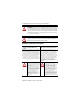
POINT I/O Input Module with 1734-TOP or 1734-TOPS Base
Description Description
1 Module locking mechanism 6 1734-TB or 1734-TBS mounting base
2 Slide-in writable label 7 Interlocking side pieces
3 Insertable I/O module 8 Mechanical keying (orange)
4 Removable terminal block (RTB) handle 9 DIN rail locking screw (orange)
5 Removable terminal block with screw
(1734-RTB) or spring clamp (1734-RTBS)
10 Module wiring diagram
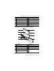
Description Description
1 Module locking mechanism 6 Interlocking side pieces
2 Slide-in writable label 7 Mechanical keying (orange)
3 Insertable I/O module 8 DIN rail locking screw (orange)
4 Removable terminal block (RTB) handle 9 Module wiring diagram
5 One-piece terminal base with screw
(1734-TOP) or spring clamp (1734-TOPS)
1
9
8
7
6
2
4
5
3
46013