
Installation Instructions Owner manual

POINT I/O™ RTD and Isolated Thermocouple Input Modules 21
Publication 1734-IN011H-EN-E - February 2014
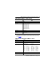
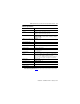
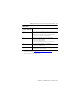
General Specifications
Attribute Value
Terminal base screw torque 0.8 Nm (7 lb-in.)
Indicators 1 green/red – module status indicator, logic side
1 green/red – network status indicator, logic side
2 green/red – input status indicators, logic side
Module location 1734-IT2I – 1734-TBCJC wiring base assembly
1734-IR2, 1734-IR2E – 1734-TB, 1734-TBS, 1734-TOP, or 1734-TOPS
wiring base assembly
POINTBus current, max @ 5V DC 1734-IT2I – 175 mA
1734-IR2, 1734-IR2E – 220 mA
Power dissipation, max 1.0 W
Thermal dissipation, max 3.3 BTU/hr
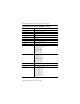
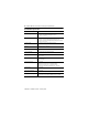
Isolation voltage 50V (continuous), Basic Insulation Type, I/O to system
Type tested at 1600V AC for 60 s
External DC power No external supply required
Dimensions, approx., HxWxD 56 x 12 x 75.5 mm
(2.21 x 0.47 x 2.97 in.)
Wiring category
(1)
1 – on signal ports
Wire size When using 1734-TBCJC, 0.25… 2.5 mm
2
(22…14 AWG) shielded
thermocouple wire, 1.2 mm (3/64 in.) insulation max
When using 1734-TB, 1734-TBS, 1734-TOP or 1734-TOPS,
0.25…2.5 mm
2
(22…14 AWG) solid or stranded shielded copper wire
rated at 75 °C (167 °F) or greater 1.2 mm (3/64 in.) insulation max
Weight, approx. 0.036 kg (0.08 lb)
IEC temperature code 1734-IR2 ,1734-IT2I – T4
North American temp code T5
Enclosure type rating None (open-style)
Keyswitch position 6
(1)
Use this conductor category information for planning conductor routing as described in Industrial Automation Wiring
and Grounding Guidelines, publication 1770-4.1
.