
Installation Instructions Owner manual
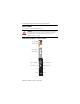

POINT I/O™ RTD and Isolated Thermocouple Input Modules 13
Publication 1734-IN011H-EN-E - February 2014
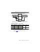
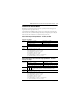
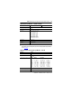
POINT I/O RTD Input Module Wiring – 1734-IR2, 1734-IR2E
POINT I/O RTD Input Module – 1734-IR2, 1734-IR2E
Channel High Signal (+) Low Signal (-) Return Shield
In 0/A 0 4 6
In 0/B 2
In 1/A 1 5 7
In 1/B 3
TIP
For improved 1734-RTB calibration wiring diagrams, refer to the POINT I/O
RTD and Isolated Thermocouple Input Modules Release Notes,
publication, 1734-RN005
.
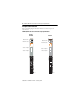
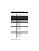
In O/A
1
0
3
2
5
4
7
6
In 1/A
In O/B In 1/B
RET 0
RET 1
ShieldShield
Two-wire
RTD
Three-wire
RTD
In = Input channel,
RET = Sensor return,
Shield = Sensor cable shield.
When using two-wire RTDs,
1
Ω resistor In/B to RET.
1 Ω
resistor