Installation Instructions POINT I/O™ RTD and Isolated Thermocouple Input Modules Catalog numbers 1734-IR2, 1734-IR2E, 1734-IT2I, Series C Table of Contents Topic Page Important User Information 2 Environment and Enclosure 3 Preventing Electrostatic Discharge 3 North American Hazardous Location Approval 4 European Hazardous Location Approval 5 About the Module 6 Install the Mounting Base 8 Install the Module 9 Install the Removable Terminal Block 10 Wire the Module 12 Communicate with
POINT I/O™ RTD and Isolated Thermocouple Input Modules Important User Information Solid-state equipment has operational characteristics differing from those of electromechanical equipment. Safety Guidelines for the Application, Installation and Maintenance of Solid State Controls (Publication SGI-1.1 available from your local Rockwell Automation sales office or online at http://www.rockwellautomation.
POINT I/O™ RTD and Isolated Thermocouple Input Modules 3 Environment and Enclosure ATTENTION: This equipment is intended for use in a Pollution Degree 2 industrial environment, in overvoltage Category II applications (as defined in IEC publication 60664-1), and at altitudes of up to 2000 m (6562 ft) without derating. This equipment is considered Group 1, Class A industrial equipment according to IEC/CISPR 11.
POINT I/O™ RTD and Isolated Thermocouple Input Modules ATTENTION: This product is grounded through the DIN rail to chassis ground. Use zinc-plated yellow-chromate steel DIN rail to assure proper grounding. The use of other DIN rail materials (for example, aluminum, plastic) that can corrode, oxidize, or are poor conductors can result in improper or intermittent grounding. Secure DIN rail to mounting surface approximately every 200 mm (7.8 in.) and use end-anchors appropriately.
POINT I/O™ RTD and Isolated Thermocouple Input Modules 5 European Hazardous Location Approval European Zone 2 Certification. The following applies when the product bears the Ex Marking. ATTENTION: This equipment is intended for use in potentially explosive atmospheres as defined by European Union Directive 94/9/EC.
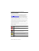
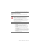
POINT I/O™ RTD and Isolated Thermocouple Input Modules About the Module You can use these Series C modules with the following: • 1734-ACNR ControlNet adapters with RSLogix 5000 software, version 11 or later • 1734-ADN, 1734-ADNX, 1734-PDN DeviceNet adapters or with any 1734D POINTBlock I/O module • 1734-AENT or 1734-AENTR EtherNet/IP adapters with RSLogix 5000 software, version 11 or later • 1734-APB PROFIBUS adapters Use this diagram to identify the external features of the module.
POINT I/O™ RTD and Isolated Thermocouple Input Modules Description 7 Description 1 Module locking mechanism 6 1734-TB or 1734-TBS mounting base 2 Slide-in writable label 7 Interlocking side pieces 3 Insertable I/O module 8 Mechanical keying (orange) 4 Removable terminal block (RTB) handle 9 DIN rail locking screw (orange) 5 Removable terminal block with screw (1734-RTB) or spring clamp (1734-RTBS) 10 Module wiring diagram POINT I/O Input Module with 1734-TOP or 1734-TOPS Base 1 2 9
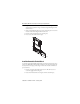
POINT I/O™ RTD and Isolated Thermocouple Input Modules Install the Mounting Base To install the mounting base on the DIN rail, proceed as follows: 1. Position the mounting base vertically above the installed units (adapter, power supply or existing module). Slide the mounting base until the interlocking side pieces engage the adjacent module or adapter. 46014 2. Slide the mounting base down allowing the interlocking side pieces to engage the adjacent module or adapter. 3.
POINT I/O™ RTD and Isolated Thermocouple Input Modules 9 ATTENTION: When you insert or remove the module while backplane power is on, an electrical arc can occur. This could cause an explosion in hazardous location installations. Be sure that power is removed or the area is nonhazardous before proceeding. Repeated electrical arcing causes excessive wear to contacts on both the module and its mating connector. Worn contacts may create electrical resistance that can affect module operation.
POINT I/O™ RTD and Isolated Thermocouple Input Modules 1. Using a bladed screwdriver, rotate the keyswitch on the mounting base clockwise until the number required for the type of module being installed aligns with the notch in the base. 2. Make certain the DIN rail locking screw is in the horizontal position. You cannot insert the module if the locking mechanism is unlocked. 3. Insert the module straight down into the mounting base.
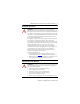
POINT I/O™ RTD and Isolated Thermocouple Input Modules 11 M Sta od tu ule s In oc pu ou t p 17 IT 34 2I 1 0 Th erm le N O N Sta etw D tus ork E: 3. If an I/O module is installed, snap the RTB handle into place on the module. Insert the module straight down into the mounting base. Hook the RTB end into the mounting base end and rotate until it locks into place.
POINT I/O™ RTD and Isolated Thermocouple Input Modules Wire the Module To wire the module, refer to the diagrams and tables. WARNING: If you connect or disconnect wiring while the field-side power is on, an electrical arc can occur. This could cause an explosion in hazardous location installations. Be sure that power is removed or the area is nonhazardous before proceeding.
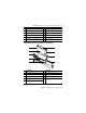
POINT I/O™ RTD and Isolated Thermocouple Input Modules 13 POINT I/O RTD Input Module Wiring – 1734-IR2, 1734-IR2E 0 1 In O/A In 1/A 3 2 Three-wire RTD In O/B In 1/B 4 5 RET 0 1Ω resistor Two-wire RTD RET 1 7 6 Shield Shield When using two-wire RTDs, 1 Ω resistor In/B to RET. In = Input channel, RET = Sensor return, Shield = Sensor cable shield.
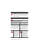
POINT I/O™ RTD and Isolated Thermocouple Input Modules 1734-IT2I Isolated Thermocouple Input Module Wiring – 1734-IT2I Module Status Module status Network Status Network status NODE: Thermocouple Input 0+ = Input channel 0 high 0- = Input channel 0 low 1+ = Input channel 1 high 1- = Input channel 1 low Status of input 0 0 Status of input 1 1 1734 IT2 3 Shield 4 0+ 0- 1+ 1- 6 5 Thermocouple 0 7 Thermocouple 1 Shield 0+ 0+ 1+ 1+ 46016 Isolated Thermocouple Input Module – 1734-IT2
POINT I/O™ RTD and Isolated Thermocouple Input Modules 15 Communicate with the Module POINT I/O modules send (produce) and receive (consume) I/O data (messages). You map this data into the processor’s memory. The 1734-IR2 and 1734-IR2E modules produce 6 bytes of input data (scanner Rx) and fault status data. The 1734-IT2I module produces 8 bytes of input data (scanner Rx) and fault status data. The modules do not consume I/O data (scanner Tx).
POINT I/O™ RTD and Isolated Thermocouple Input Modules Interpret Status Indicators Refer to the following diagram and table for information on how to interpret the status indicators.
POINT I/O™ RTD and Isolated Thermocouple Input Modules 17 Indicator Status for Modules Module status Status Description Off No power applied to device. Green Device operating normally. Flashing green Device needs commissioning due to missing, incomplete, or incorrect configuration. Flashing red Recoverable fault. Red Unrecoverable fault occurred. Self-test failure present (checksum failure, or ramtest failure at cycle power). Firmware fatal error present.
POINT I/O™ RTD and Isolated Thermocouple Input Modules Specifications POINT I/O RTD Input Modules – 1734-IR2, 1734-IR2E Attribute 1734-IR2 Number of inputs 2 single-ended, non-isolated Resolution 16 bits 9.5 mΩ/cnt 0.03 °C/cnt (Pt385 @ 25 °C) [0.05 °F/cnt (Pt385 @ 77 °F)] Input range 0…600 Ω 0…220 Ω Sensors supported 100 Ω Pt, α = 0.00385 Euro -200…870 °C (-328 … 1598 °F) 200 Ω Pt, α = 0.00385 Euro -200…630 °C (-328…1166 ° F) 100 Ω Pt, α = 0.003916 U.S.
POINT I/O™ RTD and Isolated Thermocouple Input Modules 19 POINT I/O RTD Input Modules – 1734-IR2, 1734-IR2E Attribute 1734-IR2 Common mode rejection ratio 120 dB 1734-IR2E Normal mode rejection ratio 100 dB Notch filter -3dB settable at the following: 13.1 Hz @ Notch = 50 Hz 15.7 Hz @ Notch = 60 Hz 26.2 Hz @ Notch = 100 Hz 31.4 Hz @ Notch = 120 Hz 52.4 Hz @ Notch = 200 Hz 62.9 Hz @ Notch = 240 Hz 78.6 Hz @ Notch = 300 Hz 104.8 Hz @ Notch = 400 Hz 125.
POINT I/O™ RTD and Isolated Thermocouple Input Modules POINT I/O Isolated Thermocouple Input Module – 1734-IT2I Attribute Value Input voltage ±75 mV Absolute accuracy 0.1% Full Scale @ 25 °C (77 °F) Accuracy drift with temp.
POINT I/O™ RTD and Isolated Thermocouple Input Modules 21 General Specifications Attribute Value Terminal base screw torque 0.8 Nm (7 lb-in.
POINT I/O™ RTD and Isolated Thermocouple Input Modules Environmental Specifications Attribute Value Temperature, operating IEC 60068-2-1 (Test Ad, Operating Cold), IEC 60068-2-2 (Test Bd, Operating Dry Heat), IEC 60068-2-14 (Test Nb, Operating Thermal Shock): -20…55 °C (-4…131 °F) Temperature, storage IEC 60068-2-1 (Test Ab, Unpackaged Nonoperating Cold), IEC 60068-2-2 (Test Bb, Unpackaged Nonoperating Dry Heat), IEC 60068-2-14 (Test Na, Unpackaged Nonoperating Thermal Shock): -40…85 °C (-40…185 °F)
POINT I/O™ RTD and Isolated Thermocouple Input Modules 23 Certifications Certification (when product is marked)(1) Value c-UL-us UL-listed Industrial Control Equipment, certified for US and Canada. See UL File E65584. UL-listed for Class I, Division 2 Group A,B,C,D Hazardous Locations, certified for U.S. and Canada. See UL File E194810. CE European Union 2004/108/EC EMC Directive, compliant with: EN 61326-1; Meas./Control/Lab.
Rockwell Automation Support Rockwell Automation provides technical information on the Web to assist you in using its products. At http://www.rockwellautomation.com/support/, you can find technical manuals, a knowledge base of FAQs, technical and application notes, sample code and links to software service packs, and a MySupport feature that you can customize to make the best use of these tools.