Installation Instructions POINT I/O 220V ac Input Module Catalog Numbers 1734-IM2, 1734-IM4, Series C Topic Page Important User Information 2 North American Hazardous Location Approval 3 Environment and Enclosure 4 Prevent Electrostatic Discharge 5 Before You Begin 6 Install the Mounting Base 8 Install the Module 9 Install the Removable Terminal Block (RTB) 11 Remove a Mounting Base 13 Wire the Module 14 Communicating with the Module 18 Interpret the LED Indicators 19 Specificatio
POINT I/O 220V ac Input Module Important User Information Solid state equipment has operational characteristics differing from those of electromechanical equipment. Safety Guidelines for the Application, Installation and Maintenance of Solid State Controls (publication SGI-1.1 available from your local Rockwell Automation sales office or online at http://literature.rockwellautomation.com) describes some important differences between solid state equipment and hard-wired electromechanical devices.
POINT I/O 220V ac Input Module 3 North American Hazardous Location Approval The following information applies when operating this equipment in hazardous locations. Informations sur l’utilisation de cet équipement en environnements dangereux. Products marked CL I, DIV 2, GP A, B, C, D are suitable for use in Class I Division 2 Groups A, B, C, D, hazardous locations and nonhazardous locations only.
POINT I/O 220V ac Input Module Environment and Enclosure ATTENTION This equipment is intended for use in a Pollution Degree 2 industrial environment, in overvoltage Category II applications (as defined in IEC publication 60664-1), at altitudes up to 2000 meters (6562 feet) without derating. This equipment is considered Group 1, Class A industrial equipment according to IEC/CISPR Publication 11.
POINT I/O 220V ac Input Module 5 Prevent Electrostatic Discharge ATTENTION This equipment is sensitive to electrostatic discharge, which can cause internal damage and affect normal operation. Follow these guidelines when you handle this equipment: • Touch a grounded object to discharge potential static. • Wear an approved grounding wriststrap. • Do not touch connectors or pins on component boards. • Do not touch circuit components inside the equipment. • Use a static-safe workstation, if available.
POINT I/O 220V ac Input Module Before You Begin Note that this series C product can be used with the following: • DeviceNet and PROFIBUS adapters • ControlNet and EtherNet/IP adapters, using RSLogix 5000 software, version 11 or later See the figures to familiarize yourself with major parts of the module, noting that the wiring base assembly is one of the following: • 1734-TB or 1734-TBS POINT I/O two-piece terminal base, which includes the 1734-RTB removable terminal block • 1734-TOP or 1734-TOPS POINT I
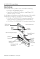
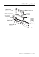
POINT I/O 220V ac Input Module 7 Module Locking Mechanism Module Wiring Diagram DIN Rail Locking Screw (orange) Mechanical Keying (orange) Interlocking Side Pieces Slide-in Writable Label Insertable I/O Module Handle 1734-TOP or 1734-TOPS One-piece Terminal Base with Screw or Spring Clamp 44221 Publication 1734-IN008C-EN-E - January 2007
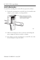
POINT I/O 220V ac Input Module Install the Mounting Base To install the mounting base on the DIN rail, proceed as follows. 1. Position the mounting base vertically above the installed units (adapter, power supply, or existing module). Slide the mounting base until the interlocking side pieces engage the adjacent module or adapter. 31586 2. Slide the mounting base down so that the interlocking side pieces engage the adjacent module or adapter. 3.
POINT I/O 220V ac Input Module 9 Install the Module The module can be installed before or after base installation. Make sure that the mounting base is correctly keyed before installing the module into the mounting base. In addition, make sure the mounting base locking screw is positioned horizontally with reference to the base. Turn the keyswitch to align the number with the notch. Notch position 3 is shown. 1734-TB base is shown. Be sure the DIN-rail locking screw is in the horizontal position.
POINT I/O 220V ac Input Module Be sure the DIN-rail locking screw is in the horizontal position. 1734-TOP base is shown. Turn the keyswitch to align the number with the notch. Notch position 1 is shown.
POINT I/O 220V ac Input Module 11 WARNING When you insert or remove the module while backplane power is on, an electrical arc can occur. This could cause an explosion in hazardous location installations. Be sure that power is removed or the area is nonhazardous before proceeding. Repeated electrical arcing causes excessive wear to contacts on both the module and its mating connector. Worn contacts may create electrical resistance that can affect module operation. 1.
POINT I/O 220V ac Input Module 3. If an I/O module is installed, snap the RTB handle into place on the module. Insert the module straight down into the mounting base. Hook the RTB end into the mounting base end and rotate until it locks into place. WARNING 44011 When you connect or disconnect the removable terminal block (RTB) with field-side power applied, an electrical arc can occur. This can cause an explosion in hazardous location installations.
POINT I/O 220V ac Input Module 13 Remove a Mounting Base To remove a mounting base, you must remove any installed module and the module installed in the base to the right. Remove the removable terminal block (RTB), if wired. 1. Unlatch the RTB handle on the I/O module. 2. Pull on the RTB handle to remove the RTB. WARNING When you connect or disconnect the removable terminal block (RTB) with field-side power applied, an electrical arc can occur.
POINT I/O 220V ac Input Module 5. Repeat steps 1…4 for the module to the right. 6. Use a small-bladed screwdriver to rotate the orange base-locking screw to a vertical position to release the locking mechanism. 7. Lift straight up to remove. Wire the Module To wire the module, refer to the figures and tables. WARNING If you connect or disconnect wiring while the field-side power is on, an electrical arc can occur. This could cause an explosion in hazardous location installations.
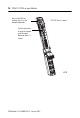
POINT I/O 220V ac Input Module 15 Wiring the Module 1734-IM2 1734-IM4 Module Status Network Status NODE: Module Status Module Status Network Status Network Status Module Status Network Status NODE: 220VAC Input Status of Input 0 0 220VAC Input Status of Input 0 0 Status of Input 1 1 Status of Input 1 1 2 Status of Input 2 3 1734 IM2 Channel 0 Connection No Connection L2/N L1 Status of Input 3 Channel 1 Connection No Connection L2/N L1 42016-OA L2/N = 220V ac Return L1 = 220V ac Supply
POINT I/O 220V ac Input Module Catalog Number 1734-IM2 0 1 Ch 0 Ch 1 2 Prox 3 NC NC L2/N L2/N L1 L1 4 Two-wire 6 Ch 0 = Channel 0 Input NC = No Connection L1 = 220V ac Prox 5 Three-wire 7 Ch 1 = Channel 1 Input L2/N = 220V ac Neutral 41966B Channel Input Terminal Return Supply 0 0 4 6 1 1 5 7 Module power is supplied from the internal power bus.
POINT I/O 220V ac Input Module 17 Catalog Number 1734-IM4 0 1 Ch 0 Ch 1 2 3 Ch2 Prox Ch3 Prox Prox Prox 4 5 L1 6 L1 L1 L1 7 L2/N L2/N Ch0 = Channel 0 Input Ch2 = Channel 2 Input L2/N = 220V ac Neutral Ch1 = Channel 1 Input Ch3 = Channel 3 Input L1 = 220V ac Common Terminal 44230 Channel Input Terminal Power 0 0 4 1 1 5 2 2 6 3 3 7 Module power is supplied from the internal power bus.
POINT I/O 220V ac Input Module Communicating with the Module I/O messages are sent to (consumed) and received from (produced) the POINT I/O modules. These messages are mapped into the processor’s memory. This POINT I/O input module produces 1 byte of input data (scanner Tx) (state). It does not consume data (scanner Rx). Refer to the table that shows the default data map.
POINT I/O 220V ac Input Module 19 Interpret the LED Indicators See the figures and tables for information about how to interpret LED indicators. 1734-IM2 1734-IM4 Module Status Module Status Network Status Network Status Status of Input 0 Status of Input 0 Status of Input 1 Status of Input 1 Status of Input 2 Status of Input 3 44211 44212 Interpret the LED Indicators State Description Recommended Action Off No power applied to device. Apply power to device.
POINT I/O 220V ac Input Module Interpret the LED Indicators State Description Recommended Action Solid Red Unrecoverable fault may require device replacement. Replace device. Flashing Red/Green Device is in self-test. None. Off Device is not online. - Device has not completed dup_MAC_id test. - Device not powered - check module status indicator. Apply power to device, wait for MAC_id to complete, and correct, as needed.
POINT I/O 220V ac Input Module 21 Specifications 220V ac Input Modules - 1734-IM2 and 1734-IM4 Attribute Value Number of Inputs 1734-IM2: 2 (1 group of 2) nonisolated, sink 1734-IM4: 2 (1 group of 4) nonisolated, sink On-state Voltage Range, Min 159V ac On-state Voltage Range, Nom 220V ac On-state Voltage Range, Max 264V ac On-state Current, Min 6.2 mA @ 159V ac, 60 Hz On-state Current, Nom 8.5 mA @ 220V ac, 60 Hz On-state Current, Max 10.
POINT I/O 220V ac Input Module General Attribute Value Module Location 1734-TB, 1734-TBS, 1734-TOP, or 1734-TOPS wiring base assembly POINTBus Current, Max 75 mA @ 5V dc Power Dissipation, Max 0.1 W @ 132V ac Thermal Dissipation, Max 3.
POINT I/O 220V ac Input Module 23 Environmental Specifications Attribute Value Temperature, Operating IEC 60068-2-1 (Test Ad, Operating Cold), IEC 60068-2-2 (Test Bd, Operating Dry Heat), IEC 60068-2-14 (Test Nb, Operating Thermal Shock): -20…55 °C (-4…131 °F) Temperature, Storage IEC 60068-2-1 (Test Ab, Unpackaged Nonoperating Cold), IEC 60068-2-2 (Test Bb, Unpackaged Nonoperating Dry Heat), IEC 60068-2-14 (Test Na, Unpackaged Nonoperating Thermal Shock): -40…85 °C (-40…185 °F) Relative Humidity IEC
Certifications Certification Value Certifications c-UL-us UL Listed Industrial Control Equipment, certified for US and Canada. See UL File E65584. UL Listed for Class I, Division 2 Group A,B,C,D Hazardous Locations, certified for U.S. and Canada. See UL File E194810. CE European Union 89/336/EEC EMC Directive, compliant with: EN 50082-2; Industrial Immunity EN 61326; Meas./Control/Lab.