Encoder/Counter Modules 1734-IJ and 1734-IK User Manual
Important User Information Solid state equipment has operational characteristics differing from those of electromechanical equipment. Safety Guidelines for the Application, Installation and Maintenance of Solid State Controls (Publication SGI-1.1 available from your local Rockwell Automation sales office or online at http://literature.rockwellautomation.com/) describes some important differences between solid state equipment and hard-wired electromechanical devices.
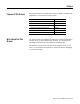
Summary of Changes This publication contains new and revised information not in the last release. New and Revised Information See the table for a summary of the major changes in this manual.
Summary of Changes 2 Notes: Publication 1734-UM006B-EN-P - August 2005
Table of Contents Preface Preface Purpose of This Manual. . . . . . . . . . . Who Should Use This Manual . . . . . . Related Products and Documentation. Definitions . . . . . . . . . . . . . . . . . . . . . . . . . . . . . . . . . . . . . . . . . . . . . . . . . . . . . . . . . . . . . . . . . . . . . . . . . . . . . . . . . . . . P-1 P-1 P-1 P-3 . . . . . . . . . . . . . . . . . . . . . . . . . . . . . . . . . . . . . . . . . . . . . . . . . . . . . . . . . . . . . . . . . . . . .
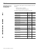
Chapter 3 Input and Output Data What This Chapter Contains . . . . . . . . . . . . . . . . . . . . . . Data Table . . . . . . . . . . . . . . . . . . . . . . . . . . . . . . . . . . . Detailed Description of Data Table Information . . . . . . . . Stored/Accumulated Channel Data (Input Word 2) . . . Module/Channel Status and Programming Error Codes (Input Words 3 and 4) . . . . . . . . . . . . . . . . . . . . . . . . Configuration Data . . . . . . . . . . . . . . . . . . . . . . . . . . . . .
Preface Purpose of This Manual Who Should Use This Manual Read this manual for information about how to install, configure and troubleshoot your Encoder/Counter module.
Preface 2 Related Products and Documentation For specification, safety approval, and other information refer to the following. • Publication Number 1734-IN005 Encoder/Counter Installation Instructions For related 1734 products and documentation see the table. Publication 1734-UM006B-EN-P - August 2005 Description Cat. No.
Preface Definitions 3 The following define the intended operation of the Encoder/Counter module.
Preface 4 Operational Mode Zero Frequency Detection Input Monitored Counter No None Encoder No None Period/Rate Yes Z Only Y A Only Rate Measurement Publication 1734-UM006B-EN-P - August 2005
Chapter 1 About the Modules What This Chapter Contains Read this chapter to learn about types, features, and capabilities of encoder/counter modules. Module Description and Features Encoder/counter modules install into the Point I/O terminal base (1734-TB or 1734-TBS) and interface with the Point I/O DeviceNet Pass-through (1734-PDN) or the Point I/O DeviceNet Adapter (1734-ADN).
1-2 About the Modules Operating Modes The encoder/counter modules operate in the modes shown in the table. Mode Description Counter Mode Read incoming single phase pulses, return a binary count Encoder Mode Read incoming 2 phase quadrature pulses, return a binary count Period/Rate Mode Count internal clocks during the On period, return a frequency Rate Measurement Mode Read pulses during the sample period, return a frequency The operation of the counter and encoder modes is nearly identical.
About the Modules 1-3 Example of Counter Mode A Input Input A B Direction Input B Z (Store Count) Input Z (Gate / Reset ) Single Phase Pulse Generator 1734-VHSC Count Up Count Down A Input B Input Outputs Updated Continuously Count 0 1 2 3 2 1 0 Encoder Mode The encoder mode reads incoming pulses and returns a binary number (0 - 16,777,215max) to the POINTBus. The encoder mode only accepts 2 phase quadrature inputs.
1-4 About the Modules EXAMPLE Example of Multiplying Encoder Mode X1 A Input A B Input B Z (Store Count) Input Z (Gate / Reset ) Quadrature Encoder 1734-VHSC Forward Rotation Reverse Rotation A Input B Input 1 2 3 2 1 0 X1 Count 1 2 3 4 1 2 3 4 5 6 7 5 6 5 4 3 2 1 0 8 7 6 5 4 3 2 1 0 X2 Count 8 9 10 11 12 11 10 9 X4 Count Outputs Updated Continuously X1 Multiplying Encoder Mode Quadrature input signals are used to count on the leading (up direction) OR trailing
About the Modules 1-5 Period / Rate Mode The Period/Rate Mode will return an incoming frequency and a total accumulated count to the POINTBus, by gating an internal 5MHz internal clock with an external signal. This mode determines the frequency and total number of input pulses by counting the number of internal 5MHz clock pulses over a user-specified number of input signal pulses. At the end of the specified number of pulses, the module returns the frequency (0 - 1 MHz).
1-6 About the Modules Relationship Between Sampled Pulses and Input Frequency Input Frequency at Z Gate/Reset Terminal Sample Pulses for 1/2 Cycle of Z Gate/Reset Pulse 2.5Hz 1M 5Hz 500k 10Hz 250k 20Hz 125k 50Hz 50k 100Hz 25k 200Hz 12.5k 500Hz 5k 1kHz 2.5k 2 Hz 1.25k 5kHz 500 10kHz 250 20kHz 125 50kHz 50 100kHz 25 Scaling the input frequency through the use of a scalar can lessen the decrease in accuracy.
About the Modules 1-7 Rate Measurement Mode The Rate Measurement mode determines the frequency and total number of input pulses over a user-specified sample period. At the end of the interval, the module returns a value representing the sampled number of pulses and a value indicating the incoming frequency. When the count and frequency update, any associated outputs are checked against their associated presets.
1-8 About the Modules New Data Indicator A two-bit counter, C1 & C0, updates every time an "event" occurs, indicating that new data is available in the Stored/Accumulated Count words. Definitions for events are as follows. • Any active gate transition in any of the Store Count (Counter or Encoder) modes • The end of the gate sample period in either the Period mode or Rate mode • The end of the programmed sample period in the Rate Measurement mode.
About the Modules Operating Mode Features 1-9 The following table summarizes which features are active in each mode: Operating Feature Counter Up / Down Encoder X1, X2 & X4 Period /Rate Rate Measurement Preset Y Y N N Rollover Y Y N N Software Reset Y Y Y Y Store Count - Z Gate / Reset 4 modes Y Y N N Scale Input Count at Z Gate / Reset N N Y N Z Gate / Reset Invert Bit Y Y Y N Sample Period N N N Y Operating Mode Features The Z Gate/Reset Terminall will operate in
1-10 About the Modules Gate/Reset terminal is high. Counting resumes on the falling edge of the pulse at the Z Gate/Reset terminal. The stored count information remains until it is overwritten with new data.
Chapter 2 Install the Module What This Chapter Contains Read this chapter for information about how to install Encoder/ Counter modules.
2-2 Install the Module ATTENTION Environment and Enclosure This equipment is intended for use in a Pollution Degree 2 industrial environment, in overvoltage Category II applications (as defined in IEC publication 60664-1), at altitudes up to 2000 meters without derating. This equipment is considered Group 1, Class A industrial equipment according to IEC/CISPR Publication 11.
Install the Module The wiring base assembly (1734-TB or 1734-TBS) consists of a mounting base (cat. no. 1734-MB) and a removable terminal block (catalog number 1734-RTB or 1734-RTBS). You can install the assembly, or just the mounting base. To install the mounting base and wiring base assembly on the DIN rail, proceed as follows. ATTENTION POINT I/O is grounded through the DIN rail to chassis ground. Use zinc-plated, yellow-chromated steel DIN rail to assure proper grounding.
2-4 Install the Module 3. Press firmly to seat the mounting base on the DIN rail. The mounting base snaps into place. M Stod ule atus Ne Stattwor us k NO DE : 0 24 So VDC Ouurce tput 1 2 3 17 OB34 4E 4. To remove the mounting base from the DIN rail: a. Remove any installed module and any module immediately to the right. b. Use a small-bladed screwdriver to rotate the DIN rail locking screw to a vertical position. This releases the locking mechanism. c. Lift straight up to remove the mounting base.
Install the Module Install the Module 2-5 Install the module before or after base installation. Make sure that you correctly key the mounting base before installing the module into the mounting base. In addition, make sure you position the mounting base locking screw horizontal, as referenced to the base. WARNING When you insert or remove the module while backplane power is on, an electrical arc can occur. This could cause an explosion in hazardous location installations.
2-6 Install the Module M St od at u us le 3 1 O 73 B 4 4E 2 1 0 2 S 4V O ou DC u t rc pu e t N N S et t w O a tu o D s rk E: The module locks into place. 44012 Install the Removable Terminal Block A removable terminal block comes with your mounting base assembly. Pull up on the RTB handle to remove, and replace as necessary without removing any of the wiring. To reinsert the removable terminal block, proceed as follows. 1. Insert the RTB end opposite the handle into the base unit.
Install the Module 2-7 3. If an I/O module is installed, snap the RTB handle into place on the module. WARNING Remove a Mounting Base When you connect or disconnect the removable terminal block (RTB) with field-side power applied, an electrical arc can occur. This could cause an explosion in hazardous location installations. Be sure that power is removed or the area is nonhazardous before proceeding. To remove a mounting base, remove any installed module and the removable terminal block (if wired). 1.
2-8 Install the Module Module Status Network Status of Input A Status of Input B Status of Input Z Input A Input Aret Input B Input Bret Input Z Input Zret Chassis Ground Chassis Ground 1 0 A 2 Aret 3 B 4 Bret 5 Zret Z 6 Publication 1734-UM006B-EN-P - August 2005 Chas Gnd 7 Chas Gnd A, B, and Z , and Aret, Bret, and Zret are inputs Chas Gnd = Chassis ground Termination Definition 0 A 1 Aret 2 B 3 Bret 4 Z 5 Zret 6 Chassis ground 7 Chassis ground 42016
Install the Module Communicate with Your Module 2-9 POINT I/O modules send (consume) and receive (produce) I/O messages. You map these messages into the processor’s memory. This module produces 6 or 10 bytes of input data (scanner Rx) (status). It consumes 1 byte of I/O data (scanner Tx). Use parameters 11 and 12 to select assembly 101, 102, or 103 for data produced by the module. When you send a configuration to the module, you check it for consistency before applying it.
2-10 Install the Module Module Configuration Parameter Set/Get Description Bytes 1 Set/Get Counter Configuration 1 2 Set/Get Filter Selection 1 3 Set/Get Decimal Position 1 4 Set/Get Reserved 1 5 Set/Get Time Base Value 2 6 Set/Get Gate Interval 1 7 Set/Get Channel Scalar 1 8 Set/Get Channel Rollover Value 4 9 Set/Get Channel Preset Value 4 10 Set/Get Counter Control Safe State 1 11 Set/Get Requested Poll Produce Assembly 1 12 Set/Get Requested Change of S
Install the Module 2-11 Filter Selection 07 06 05 04 0 ZF BF AF 03 02 01 00 FS 0 0 0 0 No Filter 0 0 0 1 50kHz (10µs + 0µs/-1.6µs) 0 0 1 0 5kHz (100µs + 0µs/-13.2µs) 0 1 0 0 500Hz (1.0ms + 0µs/-125µs) 1 0 0 0 50Hz (10ms + 0ms/-1.25ms) 0 A input not filtered 1 A input filtered 0 B input not filtered 1 B input filtered 0 Z input not filtered 1 Z input filtered Assumes a 50% duty cycle signal.
2-12 Install the Module Assemblies The Encoder and Counter Module uses several words to communicate real-time input and output data as well as non-real-time module information (for example, description, revision, etc.) and configuration. This shows the words that you can exchange. You can read (get) or write (set) data using an Explicit Message.
Chapter 3 Input and Output Data That This Chapter Contains Data Table Read this chapter to learn about the input/output data table of your 1734-IJ and 1734-IK. For more information about: See page: Data Table 3-1 Detailed Description of Data Table Information 3-2 Configuration Data 3-4 Communicate Real Time/Nonreal Time Information 3-8 See the table for a complete format of the input/output data..
3-2 Input and Output Data Detailed Description of Data Table Information Present Channel Data (Input Word 1) This is a 32 bit unsigned long word value representing the current count of the 24 bit counter (configurations: count [0], x1 encoder [1], x2 encoder [2], x4 encoder [4]) or the frequency (configurations: period/rate [5], rate measurement [7]). The range of values is 0 ≤value ≤0x00FFFFFF (16,777,215).
Input and Output Data 3-3 Bit definitions for the error code are: E10: Reserved E9: The decimal point position is outside of acceptable range. E8: Reserved E7: Reserved E6: A configuration was selected that requires the scalar and none was programmed OR Multiple scalars were selected. E5: The preset is out of range ( > 0x00FFFFFF). E4: A rollover of zero was programmed OR Rollover is out of range ( > 0x01000000).
3-4 Input and Output Data Zero frequency Detected (ZD) - This bit is operational when frequency configurations are programmed (configurations: period/rate [5], rate measurement [7]). In period/rate [5] configuration, counts are acquired during the ON state of the Z input. At very low frequencies the counter saturates, indicating a zero frequency detect. The time it takes to determine a zero frequency in these two configurations can be as long as 6.
Input and Output Data 3-5 Counter Configuration (Configuration Word 1) Use this byte to select the type of counter desired.
3-6 Input and Output Data Decimal Position (Configuration Word 3) This byte changes the significant digits of the frequency or counter display. In the frequency modes (period/rate [5], rate measurement [7]) for example, a -2 will move the decimal point left 2 places, dividing the frequency value by 100, a +1 moves it right, multiplying by 10. The firmware checks for placement to be in the range -4 ≤value ≤+2.
Input and Output Data 3-7 Scalar (Configuration Word 7) This bytel scales the Z signal in the period/rate [5] configuration. If the filter is applied, then the filtered Z is scaled. Only one bit of the scalar should be set. Selecting a scalar will cause accumulated counts to be adjusted accordingly (selecting a scalar of 128 will increase the accumulated count by 128 after 128 Z pulses have been received).
3-8 Input and Output Data Safe State Values (Configuration Word 10) When either the host transitions to PROGRAM mode or a communication fault (broken network cable) occurs, the module copies the safe state word (counter control value) into its real-time working buffer. The definitions are identical to those described under Real-time Output Data.
Chapter 4 Configure Your Module What This Chapter Contains This chapter describes how to configure your Encoder/Counter modules with RSNetworx. For more information about: Configuration Overview See page: Configuration Overview 4-1 Add the Adapter to Your Network 4-1 Add I/O Modules to Your Network 4-2 Set Counter Parameters 4-4 Check I/O Status and View the EDS File 4-6 You must use the RSNetworx for DeviceNet software to configure your module.
4-2 Configure Your Module 2. Add the communication device as shown below. (In this case, the chosen device was a 1734-ADN DeviceNet Scanner.) 1. Click here to expand the list of communication adapters. 2. Double-click here to choose the scanner. You can also click and drag the scanner name onto the network. Make sure you choose the 1734-ADN Point I/O Scanner. The scanner appears on the network. IMPORTANT The scanner must always exist on the DeviceNet network at Node 00.
Configure Your Module 4-3 The out-of-the-box node setting for 1734 modules is 63. You can change the setting by using the node commissioning tool. The node commissioning tool is available either online or offline. IMPORTANT If you commission a node on line, you must power down your system before the change takes place. 1 2 3 1. Go to the pulldown Tools. Select Node Commissioning. 2. Click on Browse. 3. Select the module to change. 4. The node commissioning dialog returns.
4-4 Configure Your Module Set Counter Parameters After adding the module to the network, you must configure the modules for use. IMPORTANT This chapter shows configuration in the online mode. Changes set in this mode take effect when you download to the individual module. 1. Configure the modules as shown below. 1. Right-click on the module. You can also left click on the module or name and the property dialog will pop up. 2. Click on Properties to configure your adapter.
Configure Your Module 4-5 Click on the Device parameters tab to get to the dialog for setting the parameters. The module’s name appears here. Type a description here. The module’s address appears here. (This field is read only.) This dialog also shows the module’s device identity. These fields are read-only. At any point, you can click here to finish changing configuration parameters. IMPORTANT: If configuration changes are made in offline mode, they do not take effect until the system goes online.
4-6 Configure Your Module To configure your module, select Configuration and modify the parameters as desired for your application. When complete, download to your module by clicking on the Download to Device button. You can download each change as you make it using “Single,” or download all your changes using “All.” Click here when finished. Check I/O Status and View the EDS File Click on the I/O Defaults tab to display the default characteristics for this module.
Configure Your Module 4-7 Click on the EDS File tab to display the statistics of the EDS file used to configure this module. Click on View File to view the actual EDS file. You can view the actual EDS file or edit the file.
4-8 Configure Your Module Notes: Publication 1734-UM006B-EN-P - August 2005
Chapter 5 Access Instantiated Instances What This Chapter Contains In this chapter, you learn how to access imbedded Instantiated Instances (assemblies) in the software. The Encoder/Counter Module uses several words to communicate real time input and output data as well as non-real time module information (such as description and revision) and configuration. These words have been preprogrammed into Instantiated Instances.
5-2 Access Instantiated Instances The Class Instance Attribute editor dialog appears. 1. Select the service code 3. Enter the class, instance and attribute here. 4. Click on Execute to initiate the action. 3. Select the Receive Data size and radix. For example: If you select Instance 101 (polled connection), the dialog looks like this. 1. Type in the instance number here. This is an example of assembly number 102 (0x66). (The class is always 4 and the attribute is always 3.) 2. Click on execute. 3.
Access Instantiated Instances Assemblies 5-3 Available assemblies are: • Assembly 101 is produced for a polled connection. • Assembly 102 is produced for a Change Of State (COS) connection. • Assemblies 103, 104 and 106 are by Explicit message only. • Assembly 105 is consumed in a polled connection . Data may be read (get) or written (set) using an Explicit Message. For example, to read the Present Channel Data, assembly 10110 (6516) can be requested.
5-4 Access Instantiated Instances #106 (0x6a) Publication 1734-UM006B-EN-P - August 2005 Set/Get Counter Configuration 1 Filter Selection 1 Decimal Position 1 Reserved 1 Time Base 2 Gate Interval 1 Scalar 1 Rollover Value 4 Preset Value 4 Counter Control SSV 1
Chapter 6 Troubleshoot the Module What This Chapter Contains Read this chapter for information about troubleshooting with the indicators. Troubleshoot with the Indicators See the figures that show the 5 indicators on the frontplate of each module. Use these indicators for troubleshooting. 1734-IJ Module Status 1734-IK Network Status Status of Input A Status of Input B Status of Input Z Indication Probable Cause Module Status 1 Off No power applied to device.
6-2 Troubleshoot the Module Indication Probable Cause Network Status Off Device is not online. - Device has not completed dup_MAC_id test. - Device not powered - check module status indicator. Flashing Green Device is online, but has no connections in the established state. Green Device online and has connections in the established state. Flashing Red One or more I/O connections are in timed-out state Red Critical link failure with failed communication device is present.
Appendix A Configure Modules in RSLogix 5000 Software What This Appendix Contains Read this appendix for information about how to configure your modules in RSLogix 5000 software, including how to complete entries on the following dialogs. • Fault/Program Action • Counter Configuration Understand Data, Connection, and Communication Formats Before you configure your modules, note the following about Data formats and Connection types. • Data format type is Integer. • Connection types are as follows.
A-2 Configure Modules in RSLogix 5000 Software When you change Connection and Data Format, note the following. • You do not delete the existing module. • You do not create a new module. • You bring forward all possible configuration data for the new setting. • Configuration data that you cannot bring forward sets to the default value. Once you apply new settings, this becomes the base configuration for the next change in Connection and Data Format settings.
Configure Modules in RSLogix 5000 Software Configure Your Module A-3 To configure your module in RSLogix 5000, complete the following. 1. Configure your adapter. Refer to the user manual for your adapter for information on how to configure the adapter and add modules to the I/O configuration to include selecting a controller and communication module. 2. Add a 1734-IJ or 1734-IK specialty module, according to the instructions in your adapter user manual. 3.
A-4 Configure Modules in RSLogix 5000 Software Work with the Fault/Program Action Dialog In Hard Run mode, you disable all controls on the Fault/Program Action, in addition to the enable and disable state for each control. Complete these entries from the dialog. 1. Check the checkboxes, as shown in the table.
Configure Modules in RSLogix 5000 Software Work with the Counter Configuration Dialog A-5 Complete entries as follows from the Counter Configuration dialog. 1. For Type, select one of the following, to set the Counter Configuration mode. • • • • Counter (default) Encoder X1, Encoder X2, or Encoder X4 Period/Rate Rate Measurement 2. Refer to the table to see what entries to complete based on what you enter for Type.
A-6 Configure Modules in RSLogix 5000 Software 3. Refer to the table to make selections for the following entries.
Configure Modules in RSLogix 5000 Software A-7 4. For Filter, select the Frequency from the following, which is the value you use to filter A/B/Z inputs when you check a corresponding checkbox. • No Filter • 50 kHz • 5 kHz • 500 Hz • 50 Hz (default) 5. Check the checkboxes for the following, which use the value you selected for Filter. • Filter A • Filter B • Filter Z 6. For Invert, check the checkbox to invert the signal at Z input, if you selected the following for Type.
A-8 Configure Modules in RSLogix 5000 Software When the value for Scalar is one of the following, frequency precision < 1. • • • • 16 32 64 128 8. Perform one of the following. • Click another tab at the top of the dialog. or • Click OK, which closes the dialog. or • Click Cancel to return to default values. or • Click Apply to save changes you made on any of the dialogs and continue to display the dialog, noting that you enable the Apply button when you make changes to any of the dialogs.
Index gate interval setting 3-6 A adding modules to the network 4-2 adding the communication device 4-2 assembly selection 3-8 B base assembly, mounting 2-1 C CE directives P-2 checking I/O status 4-6 class instance attribute editor 5-2 class instance editor 5-1 configuration 4-1 configuration, default 1-8 counter mode 1-2 counter mode operation 1-2 D data table - complete format 3-1 decimal position - frequency or counter display 3-6 default configuration 1-8 directives, European Union P-2 E encoder m
2 Index S safe state configuration 3-8 scalar 3-7 scalar operation 1-6 setting counter parameters 4-4 setting rollover counts 3-7 setting safe state values 3-8 setting the counter gate interval 3-6 setting the preset value 3-7 Publication 1734-UM006A-EN-P - August 2000 stored/accumulated channel data 3-2 V viewing EDS files 4-6 Z Z gate/reset terminal modes of operation 1-9 Z gate/reset terminal operation 1-9
How Are We Doing? Your comments on our technical publications will help us serve you better in the future. Thank you for taking the time to provide us feedback. You can complete this form and mail (or fax) it back to us or email us at RADocumentComments@ra.rockwell.com Pub. Title/Type Encoder/Counter Modules Cat. No. Pub. No. !734-IJ and 1734-IK 1734-UM006B-EN-P Pub. Date August 2005 Part No. 957974-39 Please complete the sections below.
PLEASE FASTEN HERE (DO NOT STAPLE) PLEASE FOLD HERE NO POSTAGE NECESSARY IF MAILED IN THE UNITED STATES BUSINESS REPLY MAIL FIRST-CLASS MAIL PERMIT NO.
Back Cover Publication 1734-UM006B-EN-P - August 2005 6 Supersedes Publication 1734-UM006A - August 2000 PN 957974-39 © 2005 Rockwell International Corporation. Printed in the U.S.A.