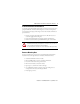
Installation Instructions POINT I/O™ 5V and 24V Encoder/Counter Modules Catalog numbers 1734-IJ, 1734-IK, Series C Table of Contents Topic Page Important User Information 2 Environment and Enclosure 3 Preventing Electrostatic Discharge 3 North American Hazardous Location Approval 4 European Hazardous Location Approval 5 Additional Resources 5 Before You Begin 6 Install the Mounting Base 7 Install the Module 8 Install the Removable Terminal Block 9 Remove a Mounting Base 9 Wire the M
POINT I/O™ 5V and 24V Encoder/Counter Modules Important User Information Solid-state equipment has operational characteristics differing from those of electromechanical equipment. Safety Guidelines for the Application, Installation and Maintenance of Solid State Controls (Publication SGI-1.1 available from your local Rockwell Automation sales office or online at http://www.rockwellautomation.
POINT I/O™ 5V and 24V Encoder/Counter Modules 3 Environment and Enclosure ATTENTION: This equipment is intended for use in a Pollution Degree 2 industrial environment, in overvoltage Category II applications (as defined in IEC publication 60664-1), at altitudes up to 2000 m (6562 ft) without derating. This equipment is considered Group 1, Class A industrial equipment according to IEC/CISPR Publication 11.
POINT I/O™ 5V and 24V Encoder/Counter Modules North American Hazardous Location Approval The following information applies when operating this equipment in hazardous locations: Informations sur l’utilisation de cet équipement en environnements dangereux: Products marked "CL I, DIV 2, GP A, B, C, D" are suitable for use in Class I Division 2 Groups A, B, C, D, Hazardous Locations and nonhazardous locations only.
POINT I/O™ 5V and 24V Encoder/Counter Modules 5 European Hazardous Location Approval European Zone 2 Certification. (The following applies when the product bears the EEx Marking) This equipment is intended for use in potentially explosive atmospheres as defined by European Union Directive 94/9/EC.
POINT I/O™ 5V and 24V Encoder/Counter Modules Before You Begin You can use these Series C POINT I/O Encoder/Counter modules with DeviceNet and PROFIBUS adapters. If you are using RSLogix 5000 software, version 11 or higher, you can also use the Series C modules with ControlNet and Ethernet adapters. Use this diagram to identify the external features of the module.
POINT I/O™ 5V and 24V Encoder/Counter Modules 7 Install the Mounting Base To install the mounting base on the DIN rail, proceed as follows: ATTENTION: This product is grounded through the DIN rail to chassis ground. Use zinc-plated, yellow-chromate steel DIN rail to assure proper grounding. The use of other DIN rail materials, for example, aluminum or plastic, that can corrode, oxidize, or are poor conductors, can result in improper or intermittent grounding.
POINT I/O™ 5V and 24V Encoder/Counter Modules Install the Module WARNING: When you insert or remove the module while backplane power is on, an electrical arc can occur. This could cause an explosion in hazardous location installations. Be sure that power is removed or the area is nonhazardous before proceeding. Repeated electrical arcing causes excessive wear to contacts on both the module and its mating connector. Worn contacts may create electrical resistance that can affect module operation.
POINT I/O™ 5V and 24V Encoder/Counter Modules 9 Install the Removable Terminal Block A removable terminal block (RTB) is supplied with your wiring base assembly. To remove, pull up the RTB handle. This allows the mounting base to be removed and replaced as necessary without removing any of the wiring. To reinsert the removable terminal block, proceed as follows: 1. Insert the end opposite the handle into the base unit. This end has a curved section that engages with the wiring base. 2.
POINT I/O™ 5V and 24V Encoder/Counter Modules Wire the Module WARNING: If you connect or disconnect wiring while the field-side power is on, an electrical arc can occur. This could cause an explosion in hazardous location installations. Be sure that power is removed or the area is nonhazardous before proceeding.
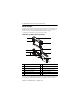
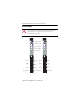
POINT I/O™ 5V and 24V Encoder/Counter Modules 11 1734-IJ and 1734-IK Wiring Diagram 0 2 Aret 3 Bret B 4 5 C 6 Termination Definition 1 A Chas gnd Cret 7 Chas gnd A, B and Z, and Aret, Bret, and Zret are inputs Chas gnd = Chassis ground 0 A 1 Aret 2 B 3 Bret 4 Z 5 Zret 6 Chassis ground 7 Chassis ground Publication 1734-IN005G-EN-E - September 2012
POINT I/O™ 5V and 24V Encoder/Counter Modules Communicate with Your Module POINT I/O modules send (consume) and receive (produce) I/O messages. You map these messages into the processor’s memory. These modules produce 6 or 10 Bytes of input data (scanner Rx) (status). These modules consume 1 Byte of I/O data (scanner Tx). Use parameters 11 and 12 to select assembly 101, 102, or 103 for data produced by the modules.
POINT I/O™ 5V and 24V Encoder/Counter Modules 13 Module Configuration Parameter Set/Get Description 1 Set/Get Counter configuration Bytes 1 2 Set/Get Filter selection 1 3 Set/Get Decimal position 1 4 Set/Get Reserved 1 5 Set/Get Time base value 2 6 Set/Get Gate interval 1 7 Set/Get Channel scalar 1 8 Set/Get Channel rollover value 4 9 Set/Get Channel preset value 4 10 Set/Get Counter control safe state 1 11 Set/Get Requested poll produce assembly 1 12 Set/Ge
POINT I/O™ 5V and 24V Encoder/Counter Modules Filter Selection(1) 07 06 05 04 03 0 ZF BF AF FS 02 01 00 0 0 0 0 No filter 0 0 0 1 50 kHz (10 μs + 0 μs/-1.6 μs) 0 0 1 0 5 kHz (100 μs + 0 μs/-13.2 μs) 0 1 0 0 500 Hz (1 ms + 0 μs/-125 μs) 1 0 0 0 50 Hz (10 ms + 0 ms/-1.25 ms) 0 A input not filtered 1 A input filtered 0 B input not filtered 1 (1) B input filtered 0 Z input not filtered 1 Z input filtered Assumes a 50% duty cycle signal.
POINT I/O™ 5V and 24V Encoder/Counter Modules 15 Assemblies Instances (Dec/Hex) Services Field Bytes #101 (0x65) Get Present channel data 4 Status 2 #102 (0x66) #103 (0x67) Get Get Stored channel data 4 Status 2 Present channel data 4 Stored channel data 4 Status 2 #104 (0x68) Get Programming error code 2 #105 (0x69) Set/Get Counter control 1 #106 (0x6a) Set/Get Counter configuration 1 #123 (0x7b) Set/Get Filter selection 1 Decimal position 1 Reserved 1 Time base
POINT I/O™ 5V and 24V Encoder/Counter Modules Interpret Status Indicators Refer to the following diagram and table for information on how to interpret the status indicators.
POINT I/O™ 5V and 24V Encoder/Counter Modules 17 Indicator Status for Modules Module status Status Description Off No power applied to device. Green Device operating normally. Flashing green Device needs commissioning due to missing, incomplete, or incorrect configuration. Flashing red Recoverable fault. Red Unrecoverable fault – may require device replacement. Flashing red/green Device is in self-test mode. Network status Off Device is not online: - Device has not completed dup_MAC-id test.
POINT I/O™ 5V and 24V Encoder/Counter Modules Specifications POINT I/O 5V and 24V Encoder/Counter Module – 1734-IJ Attribute Value Number of inputs 1 – 1 group of A/A return, B/B return and Z/Z return Input voltage 5V Input current 19.1 mA @ 5V DC 25.7 mA @ 6V DC Input off-state current, max ≤ 0.250 mA Input off-state voltage ≤ 1.25V DC Input on-state current ≥ 5 mA Input on-state voltage ≥ 2.6V DC On-state voltage, max ± 6V Input filter selections Off 10 μs 100 μs 1.0 ms 10.
POINT I/O™ 5V and 24V Encoder/Counter Modules 19 POINT I/O 5V and 24V Encoder/Counter Module – 1734-IK Attribute Value On-state voltage, max See the Input Derating Curve diagram. Input filter selections Off 10 μs 100 μs 1.0 ms 10.0 ms Input frequency, max 1.0 MHz counter and encoder X1 configurations 500 kHz encoder X2 configuration (no filter) 250 kHz encoder X4 configuration (no filter) General Specifications Attribute Value Terminal base screw torque 0.6 Nm (7 lb-in.
POINT I/O™ 5V and 24V Encoder/Counter Modules Environmental Specifications Attribute Value Temperature, operating IEC 60068-2-1 (Test Ad, Operating Cold), IEC 60068-2-2 (Test Bd, Operating Dry Heat), IEC 60068-2-14 (Test Nb, Operating Thermal Shock): -20…55 °C (-4…131 °F) Temperature, storage IEC 60068-2-1 (Test Ab, Unpackaged Nonoperating Cold), IEC 60068-2-2 (Test Bb, Unpackaged Nonoperating Dry Heat), IEC 60068-2-14 (Test Na, Unpackaged Nonoperating Thermal Shock): -40…85 °C (-40…185 °F) Relativ
POINT I/O™ 5V and 24V Encoder/Counter Modules 21 Certifications Certification (when product is marked)(1) Value c-UL-us UL Listed Industrial Control Equipment, certified for U.S. and Canada. See UL File E65584. UL Listed for Class I, Division 2, Group A,B,C,D Hazardous Locations, certified for U.S. and Canada. See UL File E194810. CE European Union 89/336/EEC EMC Directive, compliant with: EN 50082-2; Industrial Immunity EN 61326; Meas./Control/Lab.
POINT I/O™ 5V and 24V Encoder/Counter Modules Input Derating Curve 28.8 24 Input Voltage 20 (V) 10 10 20 30 40 45 50 Module Ambient Still Air Temperature (°C) 55 ATTENTION: Exceeding the maximum input voltage can cause permanent damage to the input.
POINT I/O™ 5V and 24V Encoder/Counter Modules 23 Notes: Publication 1734-IN005G-EN-E - September 2012
Rockwell Automation Support Rockwell Automation provides technical information on the Web to assist you in using its products. At http://www.rockwellautomation.com/support/, you can find technical manuals, a knowledge base of FAQs, technical and application notes, sample code and links to software service packs, and a MySupport feature that you can customize to make the best use of these tools.