
Safety Modules User Manual Owner's manual

Rockwell Automation Publication 1734-UM013J-EN-P - July 2014 95
Configure the Module in a GuardLogix Controller System Chapter 5
The channel offset can be any value from -32768…32767 (engineering
units) in increments of 1. Configure an offset when differences in the
sensors nominal input signals would otherwise exceed the desired
deadband. The channel offset is applied from the second to the first
member of the channel pair, that is, from channel 1 to channel 0 or from
channel 3 to channel 2.
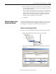
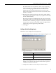
6. In the Input Error Latch Time field, enter the time the module holds an
error to make sure the controller can detect it (0…65,530 ms, in increments
of 10 ms - default 1000 ms).
This setting provides more reliable diagnostics. The purpose for latching
input errors is to make sure that intermittent faults that may exist only for a
few milliseconds are latched long enough to be read by the controller. The
amount of time to latch the errors should be based on the RPI, the safety
task watchdog, and other application-specific variables.
7. Click Apply.
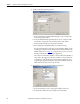
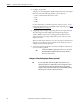
Configure the Safety Analog Inputs
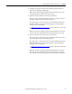
Follow these steps to configure the analog input points.
1. From the Module Properties dialog box, click the Input Configuration tab.
2. Assign the Point Mode.
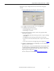
When you click Apply, channel 1 is set to the same value as channel 0 and
channel 3 is set to the same value as channel 2 if the channel operation is
configured as dual-channel equivalent.
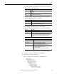
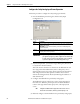
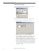
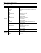
3. Configure the module for current, voltage, or tachometer inputs.
Choose Description
Not Used The input is disabled.
Safety Safety-related analog input value
Standard Standard analog input value, not being used for a safety function