
Safety Modules User Manual Owner's manual

Rockwell Automation Publication 1734-UM013J-EN-P - July 2014 79
Configure the Module in a GuardLogix Controller System Chapter 5
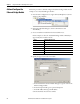
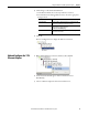
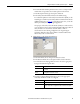
b. From the Module Number pull-down menu, choose a unique module
number that corresponds to the module’s position in the chassis.
c. In the Description field, type a description, if desired.
d. In the Safety Network Number field, use the default setting.
For a detailed explanation of the safety network number (SNN), see the
GuardLogix Controller Systems Safety Reference Manuals listed in the
Additional Resources on page 13
, noting that in most cases, you use the
default provided by the Logix Designer application.
The purpose of the safety network number (SNN) is to make sure that
every module in a system can be uniquely identified. We suggest that all
safety modules on a network have the same SNN, to make
documentation easier. During configuration, the Logix Designer
application defaults a safety device’s SNN to match the SNN of the
lowest safety node on each network.
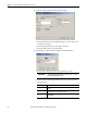
5. Click Change to edit the Module Definition.
a. In the Series field, choose the input module’s series letter.
b. In the Revision fields, choose the input module’s revision numbers.
c. From the Electronic Keying pull-down menu, choose the appropriate
keying method for the input module.
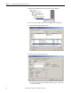
d. From the Configured By pull-down menu, choose the appropriate
method by which this module is configured.
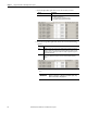
Choose Description
Exact Match All of the parameters must match or the inserted module rejects a connection to
the controller.
Compatible
Module
Allows an I/O module to determine whether it can emulate the module defined in
the configuration sent from the controller.
Choose Description
This Controller This selection directs the controller to configure the module.
External Means This selection directs the controller to establish a safety input connection only,
and the controller will not configure the module or control the Test Outputs.