
Safety Modules User Manual Owner's manual

Rockwell Automation Publication 1734-UM013J-EN-P - July 2014 59
Install the Module Chapter 4
Terminal Layout
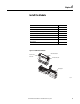
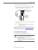
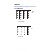
Figure 25, Figure 26, and Figure 27 on page 60 show the field wiring connections
for the POINT Guard I/O modules.
Figure 25 - 1734-IB8S Field Connections
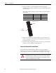
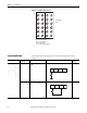
Figure 26 - 1734-OB8S Field Connections
I0 I1 I4 I5
I2 I3 I6 I7
COM COM COM COM
TO T1M T2 T3M
0
2
4
6
1
3
5
7
0
2
4
6
1
3
5
7
Where:
T0 = Test Output 0
T1M = Test Output 1 with Muting
T2 = Test Output 2
T3M = Test Output 3 with Muting
I0…I7 = Inputs 0…7
COM = Supply Common
1734-TOP and
1734-TB Bases
Shown
O0 O1 O4 O5
O2 O3 O6 O7
COM COM COM COM
COM COM COM COM
0
2
4
6
1
3
5
7
0
2
4
6
1
3
5
7
1734-TOP and
1734-TB Bases
Shown
Where:
O0…O7 = Safety Outputs 0…7
COM = Supply Common