
Safety Modules User Manual Owner's manual


Rockwell Automation Publication 1734-UM013J-EN-P - July 2014 187
Appendix E
Configuration Parameters
This appendix lists parameters that can be configured via the Logix Designer
application.
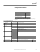
Topic Page
Table 17 Safety Digital Input Parameters 187
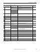
Table 18 Test Output Parameters 188
Table 19 Safety Digital Output Parameters 188
Table 20 Safety Analog Input Parameters 188
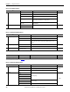
Table 17 - Safety Digital Input Parameters
Parameter Name
(1)
Value Description Default
x Input Delay Time
Off -> On
0…126 ms (in increments of
6ms)
Filter time for OFF to ON transition.
xInput Delay Time
On -> Off
0…126 ms (in increments of
6ms)
Filter time for ON to OFF transition.
x Input Point Mode Not Used External input device is not connected.
Safety Pulse Test Use with a contact output device and in combination with a test output. Using this setting, short-
circuits between input signal lines and the power supply (positive side) and short-circuits between
input signal lines can be detected.
Safety A solid-state output safety sensor is connected.
Standard A standard device, such as a reset switch, is connected.
x Safety Input Test Source Not Used The test output that is used with the input.
Test Output 0
Test Output 1
Test Output 2
Test Output 3
x Input Point Operation Type Single Channel Use as single channel.
Dual-channel Equivalent Use as dual-channel. Normal when both channels are ON or OFF.
Dual-channel Complementary Use as dual-channel. Normal when one channel is ON and the other channel is OFF.
x Safety Input Error Latch Time 0…65,530 ms
(in increments of 10 ms)
Safety input or test output errors are latched for this time. 1000 ms
(1) Parameters directly related to safety are marked with an x in the left column.