
Safety Modules User Manual Owner's manual

116 Rockwell Automation Publication 1734-UM013J-EN-P - July 2014
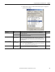
Chapter 6 Configure the Module for a SmartGuard Controller
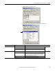
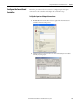
4. Double-click each Channel Safety Configuration group to display the
parameters for editing.
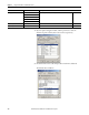
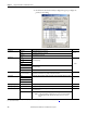
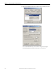
Parameter Name Value Description Default
Input Mode Not Used External input device is not connected.
Not UsedSafety A solid-state safety sensor is connected.
Standard A standard device is connected.
Input Range ±10V
Input voltage range.
4…20 mA
0…5V
0…10V
±5V
4…20 mA
Input current range.
0…20 mA
Tachometer Tachometer mode.
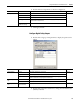
Latch Time 0…65,530 ms
(in 10 ms increments)
Safety input errors are latched for this time so that they can be read by the controller and are not
missed if they clear themselves too quickly. One value for all channels.
1000
Filter Setting 1 Hz A single-pole, anti-aliasing filter of 10Hz is followed by a four-pole digital filter with these available
frequencies.
(1)
1 Hz
5 Hz
10 Hz
50 Hz
High Engineering -30000…30000 scaling value for inputs 10000
(2)
Low Engineering -30000…30000 scaling value for inputs 0
Sensor Power Source External An external power supply is used to power the analog sensors. Terminals S0…S3 on the module
are not being used.
Module
Module Terminals S0…S3 on the module are being used to power the analog sensors.
(1) For more information on the filter frequencies and step response, see the technical specifications for the 1734-IE4S module, beginning on page 164.
(2) 1000 for Tachometer mode.
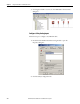
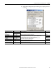
TIP
Set this value to Module to supply power to the sensors connected to the POINT
Guard Analog Input module. This allows the module to detect a loss of sensor
power.