
User guide
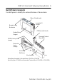
Table Of Contents
- POINT I/O 2 Current and 2 Voltage Input Analog Modules
- Inside…
- Important User Information
- Environment and Enclosure
- Preventing Electrostatic Discharge
- Before You Begin
- Identify Module Components
- Install the Mounting Base
- Install the Module
- Install the Removable Terminal Block (RTB)
- Remove a Mounting Base
- Communicate with Your Module
- Wire the Module
- Troubleshoot with Indicators
- North American Hazardous Location Approval
- European Hazardous Location Approval
- Specifications
POINT I/O 2 Current and 2 Voltage Input Analog Modules 5
Publication
1734-IN027A-EN-E - May 2005
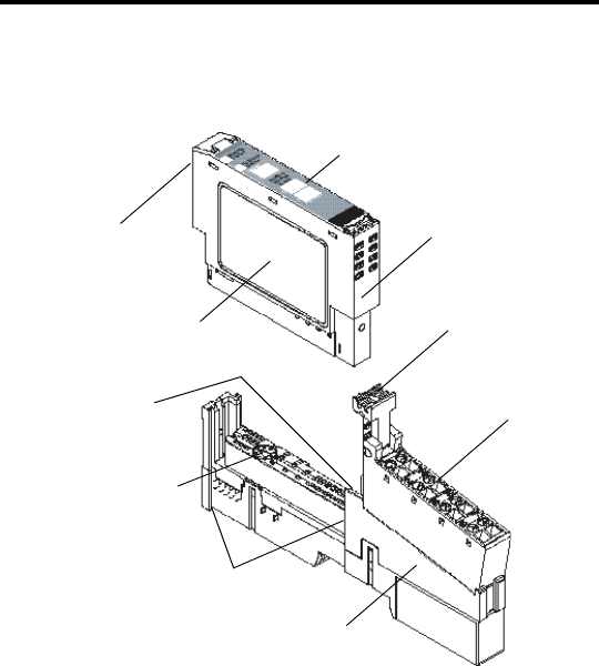
Identify Module Components
Use the figures to identify the external features of the modules.
Wiring Base Assembly is Terminal Base 1734-TB or 1734-TBS
.
43930
Interlocking
Side Pieces
DIN Rail Locking Screw
(orange)
Removable Terminal
Block (RTB)
Slide-in Writable Label
Insertable I/O
Module
Module Wiring
Diagram
Mounting Base
RTB Removable Handle
Module Locking
Mechanism
Mechanical
keying
(orange)
(Mounting Base 1734-MB and Removable Terminal Block 1734-RTB or 1734-RTBS)
.