
User guide
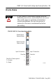
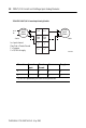
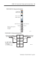
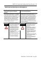
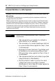
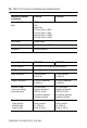
Table Of Contents
- POINT I/O 2 Current and 2 Voltage Input Analog Modules
- Inside…
- Important User Information
- Environment and Enclosure
- Preventing Electrostatic Discharge
- Before You Begin
- Identify Module Components
- Install the Mounting Base
- Install the Module
- Install the Removable Terminal Block (RTB)
- Remove a Mounting Base
- Communicate with Your Module
- Wire the Module
- Troubleshoot with Indicators
- North American Hazardous Location Approval
- European Hazardous Location Approval
- Specifications
14 POINT I/O 2 Current and 2 Voltage Input Analog Modules
Publication
1734-IN027A-EN-E - May 2005
Troubleshoot with Indicators
Use the status indicators to troubleshoot your module.
Channel Voltage Input Chassis Ground Common Supply
00 2 4 6
11 3 5 7
12/24V dc is provided by the internal field power bus.
Module Status
Network Status
Status of Input 0
Status of Input 1
1734-IE2C
POINT I/O 2 Current
Input Analog Module
41974
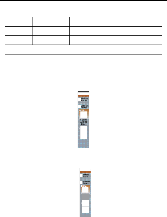
1734-IE2V
POINT I/O 2 Voltage
Input Analog Module
Module Status
Network Status
Status of Input 1
Status of Input 0
Analog
Voltage
Input