Installation Instructions POINT I/O 2 Current and 2 Voltage Input Analog Modules Catalog Numbers 1734-IE2C and 1734-IE2V, Series C Inside… For This Topic See Page Important User Information 2 Environment and Enclosure 3 Preventing Electrostatic Discharge 4 Before You Begin 4 Identify Module Components 5 Install the Mounting Base 6 Install the Module 7 Install the Removable Terminal Block (RTB) 8 Remove a Mounting Base 9 Communicate with Your Module 10 Wire the Module 11 Troubleshoot
POINT I/O 2 Current and 2 Voltage Input Analog Modules Important User Information Solid state equipment has operational characteristics differing from those of electromechanical equipment. Safety Guidelines for the Application, Installation and Maintenance of Solid State Controls (Publication SGI-1.1 available from your local Rockwell Automation sales office or online at http://literature.rockwellautomation.
POINT I/O 2 Current and 2 Voltage Input Analog Modules 3 ATTENTION Environment and Enclosure This equipment is intended for use in a Pollution Degree 2 industrial environment, in overvoltage Category II applications (as defined in IEC publication 60664-1), at altitudes up to 2000 meters without derating. This equipment is considered Group 1, Class A industrial equipment according to IEC/CISPR Publication 11.
POINT I/O 2 Current and 2 Voltage Input Analog Modules ATTENTION Preventing Electrostatic Discharge This equipment is sensitive to electrostatic discharge, which can cause internal damage and affect normal operation. Follow these guidelines when you handle this equipment: • Touch a grounded object to discharge potential static. • Wear an approved grounding wriststrap. • Do not touch connectors or pins on component boards. • Do not touch circuit components inside the equipment.
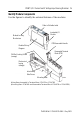
POINT I/O 2 Current and 2 Voltage Input Analog Modules 5 Identify Module Components Use the figures to identify the external features of the modules. Slide-in Writable Label Insertable I/O Module Module Locking Mechanism RTB Removable Handle Module Wiring Diagram Removable Terminal Block (RTB) DIN Rail Locking Screw (orange) Mechanical keying (orange) Interlocking Side Pieces Mounting Base 43930 Wiring Base Assembly is Terminal Base 1734-TB or 1734-TBS .
POINT I/O 2 Current and 2 Voltage Input Analog Modules Install the Mounting Base To install the mounting base on the DIN rail, proceed as follows. ATTENTION POINT I/O is grounded through the DIN rail to chassis ground. Use zinc-plated, yellow-chromated steel DIN rail to assure proper grounding. The use of DIN rail materials (e.g., aluminum, plastic, etc.) that can corrode, oxidize, or are poor conductors, can result in improper or intermittent grounding.
POINT I/O 2 Current and 2 Voltage Input Analog Modules 7 Install the Module WARNING When you insert or remove the module while backplane power is on, an electrical arc can occur. This could cause an explosion in hazardous location installations. Be sure that power is removed or the area is nonhazardous before proceeding. Repeated electrical arcing causes excessive wear to contacts on both the module and its mating connector. Worn contacts may create electrical resistance that can affect module operation.
POINT I/O 2 Current and 2 Voltage Input Analog Modules Install the Removable Terminal Block (RTB) A removable terminal block comes with your wiring base assembly. To remove, pull up on the RTB handle. You can now remove the mounting base and replace as necessary without removing any of the wiring. To reinsert the removable terminal block, proceed as follows. 1. Insert the end opposite the handle into the base unit. This end has a curved section that engages with the wiring base. 2.
POINT I/O 2 Current and 2 Voltage Input Analog Modules 9 Remove a Mounting Base To remove a mounting base, you must remove any installed module and the module installed in the base to the right. Remove the removable terminal block (if wired). 1. Unlatch the RTB handle on the I/O module. 2. Pull on the RTB handle to remove the removable terminal block. WARNING When you connect or disconnect the removable terminal block (RTB) with field-side power applied, an electrical arc can occur.
POINT I/O 2 Current and 2 Voltage Input Analog Modules 6. Use a small-bladed screwdriver to rotate the orange base locking screw to a vertical position. This releases the locking mechanism. 7. Lift straight up to remove. Communicate with Your Module POINT I/O modules send (consume) and receive (produce) I/O messages. You map these messages into the processor’s memory. This POINT I/O input module produces 6 bytes of input data (scanner Rx) and fault status data. It does not consume I/O data (scanner Tx).
POINT I/O 2 Current and 2 Voltage Input Analog Modules 11 Wire the Module WARNING If you connect or disconnect wiring while the field-side power is on, an electrical arc can occur. This could cause an explosion in hazardous location installations. Be sure that power is removed or the area is nonhazardous before proceeding.
POINT I/O 2 Current and 2 Voltage Input Analog Modules 1734-IE2C POINT I/O 2 Current Input Analog Module 0 Current Input Device ac or dc 1 In 0 In 1 Chas Gnd Chas Gnd 2 4-wire In = Input channel Chas Gnd = Chassis Ground C = Common V = 12/24V dc supply 3 4 6 Current Input Device 2-wire 5 C C V V 7 42018in Channel Current Input Chassis Ground Common Supply 0 0 2 4 6 1 1 3 5 7 12/24V dc is provided by the internal field power bus.
POINT I/O 2 Current and 2 Voltage Input Analog Modules 13 1734-IE2V POINT I/O 2 Voltage Input Analog Module Module Status Network Status Analog Voltage Input Status of Input 0 Status of Input 1 Input 1 Connection Input 0 Connection Chas Gnd Chas Gnd = Chassis ground C = Common V = Supply Chas Gnd C C V V 41974 1734-IE2V POINT I/O 2 Voltage Input Analog Module Voltage Input 0 1 In 0 In 1 Chas Gnd Chas Gnd 2 3 4 In = Input channel Chas Gnd = Chassis Ground C = Common V = 12/24V dc supply
POINT I/O 2 Current and 2 Voltage Input Analog Modules Channel Voltage Input Chassis Ground Common Supply 0 0 2 4 6 1 1 3 5 7 12/24V dc is provided by the internal field power bus. Troubleshoot with Indicators Use the status indicators to troubleshoot your module.
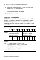
POINT I/O 2 Current and 2 Voltage Input Analog Modules 15 Indication Probable Cause Module Status Off No power applied to device Green Device operating normally Flashing Green Device needs commissioning due to configuration missing, incomplete or incorrec. Flashing Red Recoverable fault Red Unrecoverable fault may require device replacement Flashing Red/Green Device is in self-test Indication Probable Cause Network Status Off Device is not online - Device has not completed dup_MAC_id test.
POINT I/O 2 Current and 2 Voltage Input Analog Modules Indication Probable Cause Channel Status Off Module in CAL mode Solid Green Normal (channel scanning inputs) Flashing Green Channel being calibrated Solid Red No power or major channel fault Flashing Red Channel at end of range (0mA or 21mA) for 1734-IEC2C Channel at end of range (over or under) for 1734-IE2V Publication 1734-IN027A-EN-E - May 2005
POINT I/O 2 Current and 2 Voltage Input Analog Modules 17 North American Hazardous Location Approval The following information applies when operating this equipment in hazardous locations: Informations sur l’utilisation de cet équipement en environnements dangereux: Products marked “CL I, DIV 2, GP A, B, C, D” are suitable for use in Class I Division 2 Groups A, B, C, D, Hazardous Locations and nonhazardous locations only.
POINT I/O 2 Current and 2 Voltage Input Analog Modules European Hazardous Location Approval European Zone 2 Certification (The following applies when the product bears the EEx marking) This equipment is intended for use in potentially explosive atmospheres as defined by European Union Directive 94/9/EC.
POINT I/O 2 Current and 2 Voltage Input Analog Modules 19 Specifications Input Specifications 1734-IE2C 1734-IE2V Number of Inputs 2 single-ended, non-isolated Input Resolution, Bits 16 bits - over 0-21mA 0.32µA/cnt 15 bits plus sign 320µV/cnt in unipolar or bipolar mode Input Current 4-20mA 0-20mA - Input Voltage - 0-10V (user configurable) (-0.0V under, +0.5V over) +10V user configurable (-0.5V under, +0.5V over) Absolute Accuracy1 Current or Voltage Input 0.
POINT I/O 2 Current and 2 Voltage Input Analog Modules Input Specifications (continued) 1734-IE2C Normal Mode Rejection Ratio -60dB -3db Notch filter 15.7Hz @ Notch = 60Hz 13.1Hz @ Notch = 50Hz 65.5Hz @ Notch = 250Hz 131Hz @ Notch = 500Hz Data Format Signed integer Maximum Overload Fault protected to 28.8V dc Calibration Factory calibrated General Specifications 1734-IE2C Module Location 1734-TB or 1734-TBS wiring base assembly POINTBus Current 75mA @5V dc Power Dissipation 0.
POINT I/O 2 Current and 2 Voltage Input Analog Modules 21 General Specifications (continued) 1734-IE2C Indicators 1 green/red network status indicator, logic side 1 green/red module status indicator, logic side 2 green/red input status indicators, logic side Keyswitch Position 3 Dimensions 2.21H x 0.47W x 2.97L (56H x 12W x 75.
POINT I/O 2 Current and 2 Voltage Input Analog Modules General Specifications (continued) 1734-IE2C 1734-IE2V ESD Immunity IEC6100-4-2: 6kV contact discharges 8kV air discharges Radiated RF Immunity IEC 61000-4-3: 10V/m with 1kHz sine-wave 80%AM from 30MHz to 2000MHz 10V/m with 200Hz 50% Pulse 100%AM at 900Mhz 10V/m with 200Hz 50% Pulse 100%AM at 1890MHz EFT/B Immunity IEC 61000-4-4: ±3kV at 5.
POINT I/O 2 Current and 2 Voltage Input Analog Modules 23 Certification3 (when product is marked) 1734-IE2C c-UL-us UL Listed Industrial Control Equipment, certified for U.S. and Canada UL Listed for Class I, Division 2 Group A,B,C,D Hazardous Locations, certified for U.S. and Canada X X X CE European Union 89/336/EEC EMC Directive, compliant with: EN 50082-2; Industrial Immunity EN 61326; Meas./Control/Lab.
Rockwell Automation Support Rockwell Automation provides technical information on the web to assist you in using its products. At http://support.rockwellautomation.com, you can find technical manuals, a knowledge base of FAQs, technical and application notes, sample code and links to software service packs, and a MySupport feature that you can customize to make the best use of these tools.