Installation Instructions POINT I/O Input Modules Catalog numbers 1734-IB2, 1734-IB4, 1734-IB8, Series C Table of Contents Topic Page Important User Information 2 Environment and Enclosure 3 Preventing Electrostatic Discharge 3 North American Hazardous Location Approval 4 European Hazardous Location Approval 5 Before You Begin 6 About the Module 7 Install the Mounting Base 7 Install the Module 8 Install the Removable Terminal Block 9 Remove a Mounting Base 10 Communicate with Your M
POINT I/O Input Modules Important User Information Solid-state equipment has operational characteristics differing from those of electromechanical equipment. Safety Guidelines for the Application, Installation and Maintenance of Solid State Controls (Publication SGI-1.1 available from your local Rockwell Automation sales office or online at http://www.rockwellautomation.com/literature/) describes some important differences between solid-state equipment and hard-wired electromechanical devices.
POINT I/O Input Modules 3 Environment and Enclosure ATTENTION: This equipment is intended for use in a Pollution Degree 2 industrial environment, in overvoltage Category II applications (as defined in IEC 60664-1), at altitudes up to 2000 m (6562 ft) without derating. This equipment is considered Group 1, Class A industrial equipment according to IEC/CISPR 11.
POINT I/O Input Modules North American Hazardous Location Approval The following information applies when operating this equipment in hazardous locations: Informations sur l’utilisation de cet équipement en environnements dangereux: Products marked "CL I, DIV 2, GP A, B, C, D" are suitable for use in Class I Division 2 Groups A, B, C, D, Hazardous Locations and nonhazardous locations only. Each product is supplied with markings on the rating nameplate indicating the hazardous location temperature code.
POINT I/O Input Modules 5 European Hazardous Location Approval The following applies when the product bears the Ex Marking This equipment is intended for use in potentially explosive atmospheres as defined by European Union Directive 94/9/EC.
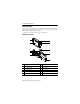
POINT I/O Input Modules Before You Begin You can use these Series C POINT I/O™ Input Modules with DeviceNet and PROFIBUS adapters. If you are using RSLogix 5000 software, version 11 or higher, you can also use the modules with ControlNet and Ethernet adapters. Use this diagram to identify the external features of the module.
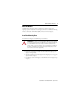
POINT I/O Input Modules 7 About the Module The POINT I/O sink input modules are available in two-input, four-input, and eight-input options. They install on mounting bases that mount on a DIN rail. All wiring is made to a Removable Terminal Block (RTB) mounted on the mounting base. Install the Mounting Base To install the mounting base on the DIN rail, proceed as follows: ATTENTION: This product is grounded through the DIN rail to chassis ground.
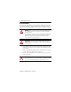
POINT I/O Input Modules Install the Module The module can be installed before or after base installation. Make sure that the mounting base is correctly keyed before installing the module into the mounting base. In addition, make sure the mounting base locking screw is positioned horizontal referenced to the base. WARNING: When you insert or remove the module while backplane power is on, an electrical arc can occur. This could cause an explosion in hazardous location installations.
POINT I/O Input Modules 9 Install the Removable Terminal Block A Removable Terminal Block (RTB) is supplied with your wiring base assembly. This allows the mounting base to be removed and replaced as necessary without removing any of the wiring. To insert the Removable Terminal Block, proceed as follows: 1. Insert the end opposite the handle into the base unit. This end has a curved section that engages with the wiring base. 2. Rotate the terminal block into the wiring base until it locks itself in place.
POINT I/O Input Modules Remove a Mounting Base To remove a mounting base, you must remove any installed module, and the module installed in the base to the right. Remove the Removable Terminal Block, if wired. 1. Unlatch the RTB handle on the I/O module. 2. Pull on the RTB handle to remove the Removable Terminal Block. 3. Press on the module lock on the top of the module. 4. Pull on the I/O module to remove from the base. 5. Repeat steps 1, 2, 3 and 4 for the module to the right. 6.
POINT I/O Input Modules 11 Communicate with Your Module I/O messages are sent to (consumed) and received from (produced) the POINT I/O modules. These messages are mapped into the processor’s memory. This POINT I/O input module produces 1 Byte of input data (scanner Rx). It does not consume I/O data (scanner Tx).
POINT I/O Input Modules Wire the Module 1734-IB2 1734-IB4 Module Status Module status Network Status Network status Module Status NODE: NODE: 24VDC Sink Input Status of input 0 0 1 Status of input 1 1 Status of input 2 Status of input 3 1734 IB2 NC Network Status Network Status 0 Input 0 Module Status NODE: 24VDC Sink Input Status of input 0 Status of input 1 1734-IB8 Status of inputs 0 & 4 Status of inputs 1 & 5 Status of inputs 2 & 6 Status of inputs 3 & 7 2 3 1734 IB4 24VD
POINT I/O Input Modules 13 WARNING: If you connect or disconnect wiring while the field-side power is on, an electrical arc can occur. This could cause an explosion in hazardous location installations. Be sure that power is removed or the area is nonhazardous before proceeding. WARNING: To comply with the CE Low Voltage Directive (LVD), this equipment must be powered from a source compliant with the following: Safety Extra Low Voltage (SELV) or Protected Extra Low Voltage (PELV).
POINT I/O Input Modules Wiring for 1734-IB4 – Sink Input 0 1 In 0 3-wire 2-wire 2 3 In 2 Prox Prox In 1 In 3 4 5 C 6 V = 12/24V DC C = Common Prox Prox C 7 V V Channel Input Common Voltage 0 0 4 6 1 1 5 7 2 2 4 6 3 3 5 7 Connect common on 3-wire proximity switches.12/24V DC is supplied through the internal power bus.
POINT I/O Input Modules 15 Wiring for 1734-IB8 – Sink Input 3-wire Prox 2-wire Prox 3-wire Prox V = 12/24V DC C = Common 2-wire Prox V 0 1 In 0 In 1 2 3 In 2 In 3 4 5 In 4 In 5 6 7 In 6 In 7 3-wire Prox 2-wire Prox 3-wire Prox 2-wire Prox C C Channel Input Channel Input 0 0 4 4 1 1 5 5 2 2 6 6 3 3 7 7 V Daisychain common and power connections from 1734 adapter, 1734-FPD, 1734-EP24DC, or from user-supplied external auxiliary terminal block.
POINT I/O Input Modules Wiring Example for 1734-IB8 Using 2-Wire Proximity Switches DeviceNet System Power DeviceNet Power Module Status Module Status Network Status Network Status 0 4 0 4 1 5 1 5 2 6 2 6 3 7 3 1734 OB8E 7 1734 IB8 Prox Prox Prox Prox Prox Prox Prox Prox 24V DC return 24V DC Terminal block with bus connector strip Publication 1734-IN051H-EN-E - April 2013 45724
POINT I/O Input Modules 17 Wiring Example for 1734-IB8 Using 3-Wire Proximity Switches DeviceNet System Power DeviceNet Power Module Status Module Status Network Status Network Status 0 4 0 4 1 5 1 5 2 6 2 6 3 7 3 1734 OB8E 7 1734 IB8 Prox Prox Prox Prox Prox Prox Prox Prox 24V DC return 24V DC Terminal block with bus connector strip Terminal block with bus connector strip 45725 Publication 1734-IN051H-EN-E - April 2013
POINT I/O Input Modules Interpret Status Indicators Refer to the following diagram and table for information on how to interpret the status indicators.
POINT I/O Input Modules 19 Indicator Status for Modules Module status Status Description Off No power applied to device. Green Device operating normally. Flashing green Device needs commissioning due to missing, incomplete, or incorrect configuration. Flashing red Recoverable fault. Red Unrecoverable fault – may require device replacement. Flashing red/green Device is in self-test mode. Network status Off Device is not online: - Device has not completed dup_MAC-id test.
POINT I/O Input Modules Specifications POINT I/O Input Module – 1734-IB2, 1734-IB4, 1734-IB8 Attribute Value Inputs per module 1734-IB2 – 2 (1 group of 2), sinking 1734-IB4 – 4 (1 group of 4), sinking 1734-IB8 – 8 (1 group of 8), sinking Voltage, on-state, min 10V DC Voltage, on-state, nom 24V DC Voltage, on-state, max 28.8V DC Current, on-state, min 2 mA Current, on-state, nom 4 mA @ 24V DC Current, on-state, max 5 mA Voltage, off-state, max 5V DC Current, off-state, min 1.
POINT I/O Input Modules 21 General Specifications(1) Attribute Value Indicators, module status 1 green/red, logic side Indicators, input status 1734-IB2 – 2 yellow, logic side 1734-IB4 – 4 yellow, logic side 1734-IB8 – 8 yellow, logic side POINTBus current, max 75 mA @ 5V DC Power dissipation @ 28.8V DC, max 1734-IB2 – 0.7 W 1734-IB4 – 1.0 W 1734-IB8 – 1.6 W Thermal dissipation @ 28.8V DC, max 1734-IB2 – 2.4 BTU/hr 1734-IB4 – 3.4 BTU/hr 1734-IB8 – 5.
POINT I/O Input Modules Environmental Specifications Attribute Value Temperature, operating IEC 60068-2-1 (Test Ad, Operating Cold), IEC 60068-2-2 (Test Bd, Operating Dry Heat), IEC 60068-2-14 (Test Nb, Operating Thermal Shock): -20...55 °C (-4...131 °F) Temperature, surrounding air, max.
POINT I/O Input Modules 23 Certifications Certification (when product is marked)(1) Value c-UL-us UL-listed Industrial Control Equipment, certified for US and Canada. See UL File E65584. UL Listed for Class I, Division 2 Group A,B,C,D Hazardous Locations, certified for U.S. and Canada. See UL File E194810. CE European Union 2004/108/EC EMC Directive, compliant with: EN 61326-1; Meas./Control/Lab.
Rockwell Automation Support Rockwell Automation provides technical information on the Web to assist you in using its products. At http://www.rockwellautomation.com/support/, you can find technical manuals, a knowledge base of FAQs, technical and application notes, sample code and links to software service packs, and a MySupport feature that you can customize to make the best use of these tools.