Installation Instructions POINT I/O Field Potential Distributor Modules Catalog number 1734-FPD, Series B Table of Contents Topic Page Important User Information 2 Environment and Enclosure 3 Preventing Electrostatic Discharge 3 North American Hazardous Location Approval 4 European Hazardous Location Approval 5 About the Module 6 Install the Module 7 Remove the Module 8 Replace the Module 8 Wire the Module 9 Specifications 12
POINT I/O Field Potential Distributor Modules Important User Information Solid-state equipment has operational characteristics differing from those of electromechanical equipment. Safety Guidelines for the Application, Installation and Maintenance of Solid State Controls (Publication SGI-1.1 available from your local Rockwell Automation sales office or online at http://www.rockwellautomation.
POINT I/O Field Potential Distributor Modules 3 Environment and Enclosure ATTENTION: This equipment is intended for use in a Pollution Degree 2 industrial environment, in overvoltage Category II applications (as defined in IEC publication 60664-1), at altitudes up to 2000 meters (6562 ft) without derating. This equipment is considered Group 1, Class A industrial equipment according to IEC/CISPR Publication 11.
POINT I/O Field Potential Distributor Modules North American Hazardous Location Approval The following information applies when operating this equipment in hazardous locations: Informations sur l’utilisation de cet équipement en environnements dangereux: Products marked "CL I, DIV 2, GP A, B, C, D" are suitable for use in Class I Division 2 Groups A, B, C, D, Hazardous Locations and nonhazardous locations only.
POINT I/O Field Potential Distributor Modules 5 European Hazardous Location Approval The following applies when the product bears the Ex Marking This equipment is intended for use in potentially explosive atmospheres as defined by European Union Directive 94/9/EC.
POINT I/O Field Potential Distributor Modules About the Module The purpose of the POINT I/O™ Field Potential Distributor module is to break the field power distribution. Use the module to change the field power distribution source for I/O modules to the right of the module. This facilitates logical or functional partitioning of low-channel count, high I/O-mix applications using the 1734-adapters, 1734-PDN, and 1734D Series communication interfaces.
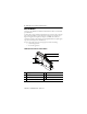
POINT I/O Field Potential Distributor Modules 7 Install the Module To install the module on the DIN rail, proceed as follows: 1. Position the module vertically above the DIN rail. 2. Engage the interlocking pieces with the unit on the left. 3. Press down firmly to install the module on the DIN rail. The locking mechanism locks the module to the DIN rail. ATTENTION: This product is grounded through the DIN rail to chassis ground. Use zinc plated yellow-chromate steel DIN rail to assure proper grounding.
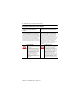
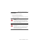
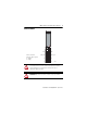
POINT I/O Field Potential Distributor Modules Remove the Module To remove a 1734-FPD module, you must first remove any I/O module installed in the base to the right. To remove the 1734-FPD module from the DIN rail, proceed as follows: 1. Pull up on the RTB removal handle to remove the terminal block. 45727 2. Use a small-bladed screwdriver to rotate the DIN rail locking screw to a vertical position. This releases the locking mechanism. 3. Lift straight up to remove.
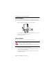
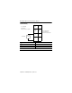
POINT I/O Field Potential Distributor Modules 9 Wire the Module NC NC = No connection Chas gnd = Chassis ground C = Common V = Supply Chas gnd NC Chas gnd C C V V 45728 WARNING: If you connect or disconnect wiring while the field-side power is on, an electrical arc can occur. This could cause an explosion in hazardous location installations. Be sure that power is removed or the area is nonhazardous before proceeding. ATTENTION: Do not wire more than 2 conductors on any single terminal.
POINT I/O Field Potential Distributor Modules 12/24V DC Wiring 0 V = 12/24V DC C = Common Chas gnd = Chassis ground 1 NC NC 2 3 Chas gnd Chas gnd C C 4 12/24V DC V DC 5 6 7 V Connect Terminal +V DC 6 -V DC 4 Chas gnd 2 V 12/24V DC becomes the internal field power bus for modules to the right. Publication 1734-IN059D-EN-E - April 2013 This supply will be connected to the internal field power bus.
POINT I/O Field Potential Distributor Modules 11 120/240V AC Wiring 0 L2/N = Neutral L1 = 120/240V AC Chas gnd = Chassis ground 1 NC NC Chas gnd Chas gnd 2 3 4 5 L2/N 12/24V AC V AC This supply will be connected to the internal field power bus. L2/N 6 7 L1 Connect Terminal L1 6 L2/N 4 Chas gnd 2 L1 120/240V AC becomes the internal power bus for modules to the right.
POINT I/O Field Potential Distributor Modules Specifications General Specifications Attribute Value Terminal base screw torque 0.8 Nm (7 lb-in.) Module location Between I/O modules in 1734 system Breaks power bus Indicators None POINTBus current Pass through Power consumption None Power dissipation None Thermal dissipation None Isolation voltage 250V (continuous), Basic Insulation Type Type tested @ 2600V DC for 60 s, User power to system, User power to Chassis ground.
POINT I/O Field Potential Distributor Modules 13 Environmental Specifications Attribute Value Temperature, operating IEC 60068-2-1 (Test Ad, Operating Cold), IEC 60068-2-2 (Test Bd, Operating Dry Heat), IEC 60068-2-14 (Test Nb, Operating Thermal Shock): -20...55 °C (-4...
POINT I/O Field Potential Distributor Modules Certifications Certification (when product is marked)(1) Value c-UL-us UL-listed Industrial Control Equipment, certified for US and Canada. See UL File E65584. UL Listed for Class I, Division 2 Group A,B,C,D Hazardous Locations, certified for U.S. and Canada. See UL File E194810. CE European Union 89/336/EEC EMC Directive, compliant with: EN 61326-1; Meas./Control/Lab.
POINT I/O Field Potential Distributor Modules 15 Notes: Publication 1734-IN059D-EN-E - April 2013
Rockwell Automation Support Rockwell Automation provides technical information on the Web to assist you in using its products. At http://www.rockwellautomation.com/support/, you can find technical manuals, a knowledge base of FAQs, technical and application notes, sample code and links to software service packs, and a MySupport feature that you can customize to make the best use of these tools.